Introduction
This is the official documentation of the Quori robot v1.
Quori owners should refer to the Usage section, to learn about the robot's maintenance and operation. See also the assembly instructions if you have just received a robot.
If the robot is already setup, and developers should refer to the Software section.
Development Team
The Quori Team is a collaboration between the University of Pennsylvania (UPenn) Modlab and the University of California (USC) Interaction Lab. USC and UPenn are joined by Semio, a social robotics software company.
This project is supported by the National Science Foundation (NSF) Computing Research Infrastructure (CRI) Collaborative grant CNS-1513275 and CNS-1513108.
Technical Support
Quori’s modular architecture is intended to enable users to easily maintain and upgrade the hardware without need for custom maintenance or support personnel. Support for each robot will be available for up to one (1) year from its delivery. All awarded research teams are invited to send personnel to the University of Pennsylvania to receive hardware training and support, and/or to Semio for software training and support. Semio software and support will be available under free for fair use terms to non-commercial users.
Quori v1
A Modular Robot Platform for Enabling Computing Research in Socially Intelligent Human-Robot Interaction.
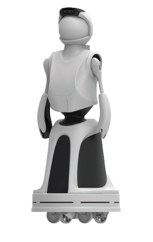
Quori is a novel, socially interactive robot for facilitating non-contact human-robot interaction (HRI) research, both in the lab and in the wild. Quori aims to provide an affordable, high-quality platform that allows HRI researchers to conduct meaningful user studies by deploying systems in the real world. The Quori platform includes both hardware and software to help facilitate HRI. Quori was designed and produced with support from the National Science Foundation Computing Research Infrastructure grant, which included the support for ten Quori platforms to be distributed to researchers in a competitive project proposal process
See the Usage section for more information on how to use Quori.
Community-Informed Hardware
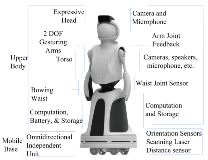
The following design of Quori is a result of the computing community input over three years of surveys and workshops. Quori is a low-cost, socially interactive robot platform comprised of an upper-body humanoid with a rear-projection head/face and two gesturing arms mounted atop an omnidirectional mobile base, standing at approximately 1.4 meters tall.
Sensors are integrated to provide useful data for recognizing and making decisions about interactions with both the environment and human users. The robot is designed for non-contact HRI tasks, such as person-tracking, performing expressive arm gestures, and displaying expressive facial features.
The hardware has an extensible yet simple software architecture and a standard mechanical and electrical interface for actuated and passive hardware elements. The software design involves novel general algorithms and robust code bases that enable the hardware platform to operate “out of the box” with a set of social behavior primitives enabling computing researchers to focus on their areas of interest without having to develop low-level robot control algorithms and code. Further information can be found at http://www.quori.org/about-quori and our journal paper. DOI: 10.1109/TRO.2021.3111718 You can find the article on IEEE Xplore or on ArXiv incase it is still being published: https://arxiv.org/abs/2109.00662
More details on the hardware can be found in the Hardware section.
Usage
Safety
- Make sure your robot is off (the main breaker) before modifying any power configuration.
- The robot should be off if you are servicing any part of the robot. Make sure the motor Emergency stop is engaged (pushed down).
- Make sure all panels are on while operating the robot. This will prevent the robot and bystanders from getting hurt.
- Do not backdrive the arms. If you need to reposition the arms then make sure you power off the motors and move the shoulder at the gear and not the hand or arm. If you backdrive the arm by the hand or arm it will stress and wear down the arm gears and transmission and may lead to a break.
Powering On
These instructions assume your robot is in the default configuration and your robot is fully assembled as described in the Assembly/Disassembly section.
Make sure the Emergency Stop is push in. This will prevent power to the motors.
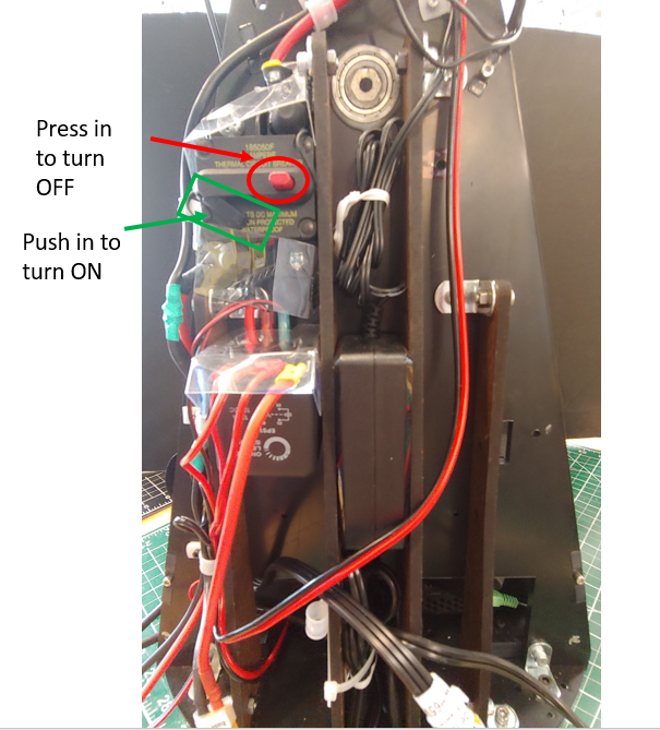
Push in the red switch on the main breaker of Quori. You will need to remove the back service panel to access this.
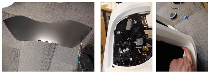
To turn the PC on you will press the PC power button (for one second) on the front right of the robot.
When you are ready to power the motors on you can twist the Emergency Stop button to release the switch.
If the robot does NOT make SERIES OF BEEPS when booting up, the motors will not run! If this happens, press the e-stop then twist to release it. Repeat this until you hear the series of beeps.
Powering Off
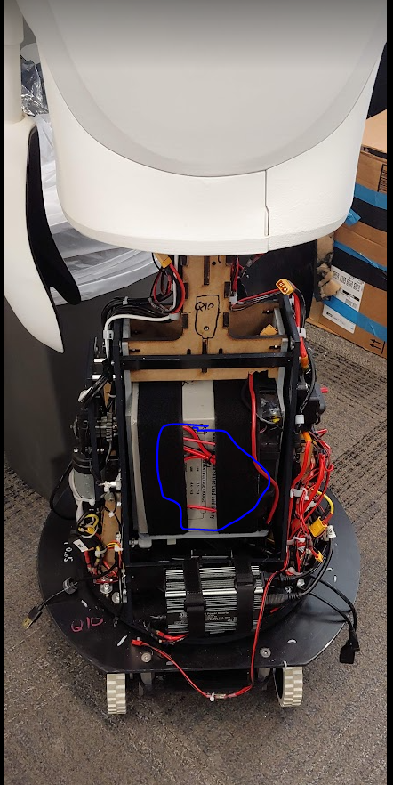
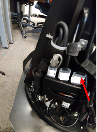
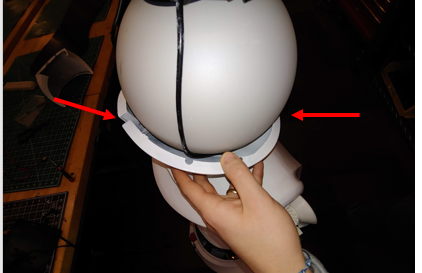
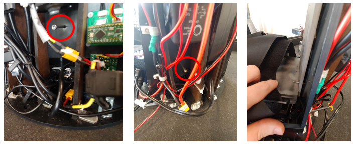
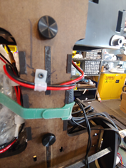
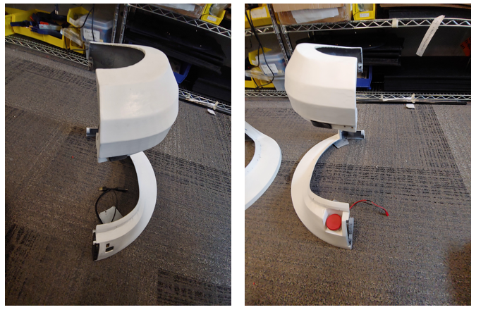
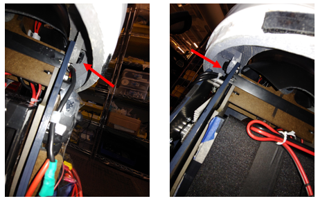
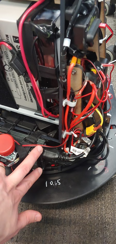
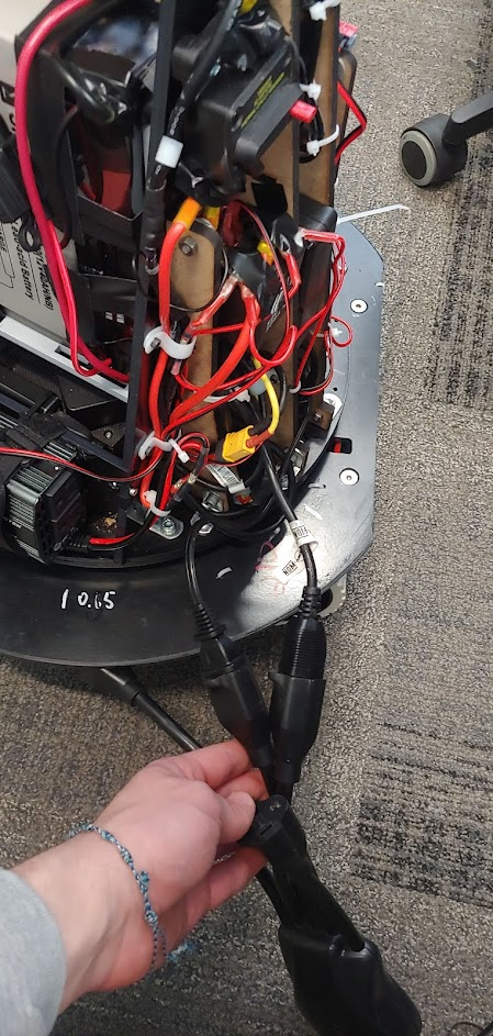
- Peel off the black siding around the base of the robot.
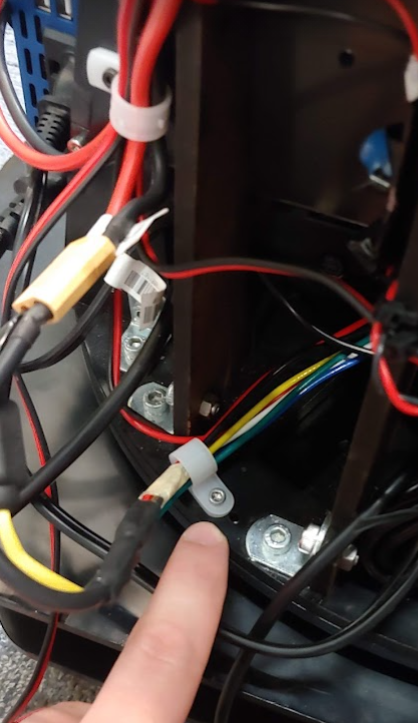
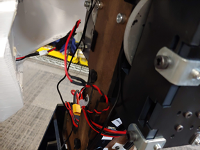
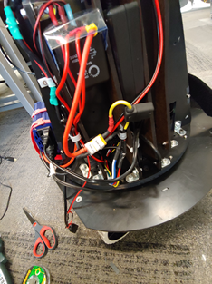
- On the robot's right hand side there is a small box with a red button and black lever (see area marked in red in the picture above). Press the red button.
- Put the black siding back on the robot.
Recharging
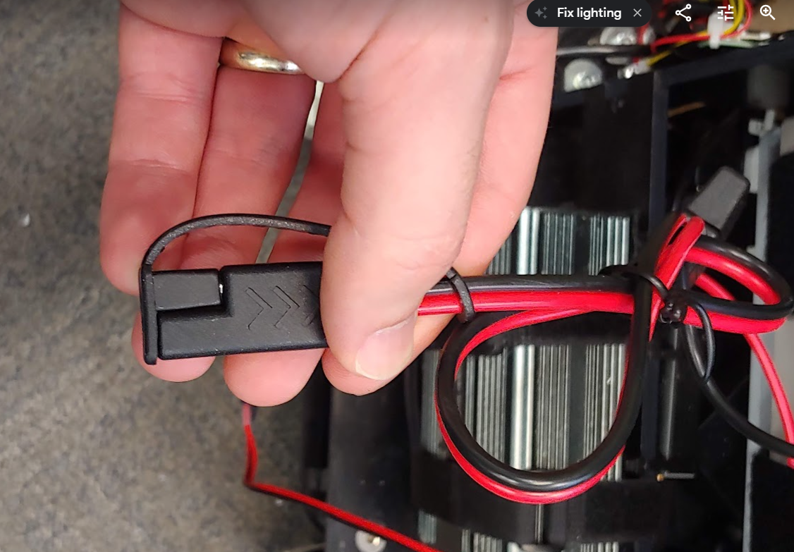
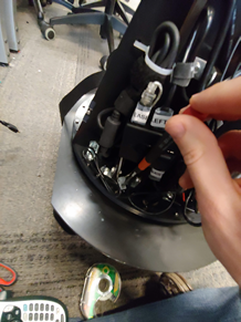
The robot battery can be charged while mounted in the robot. Use the bullet connector cable that should be tucked under the battery velcro straps. Besure to secure the charger cable under the velcro when you are done charging. You will need to remove at least one of the black service panels to access the charging cable.
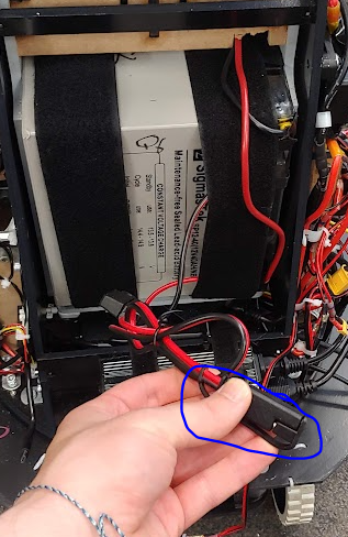
Next plug the charger into the battery cable. Do not plug the charger into AC power before this step.
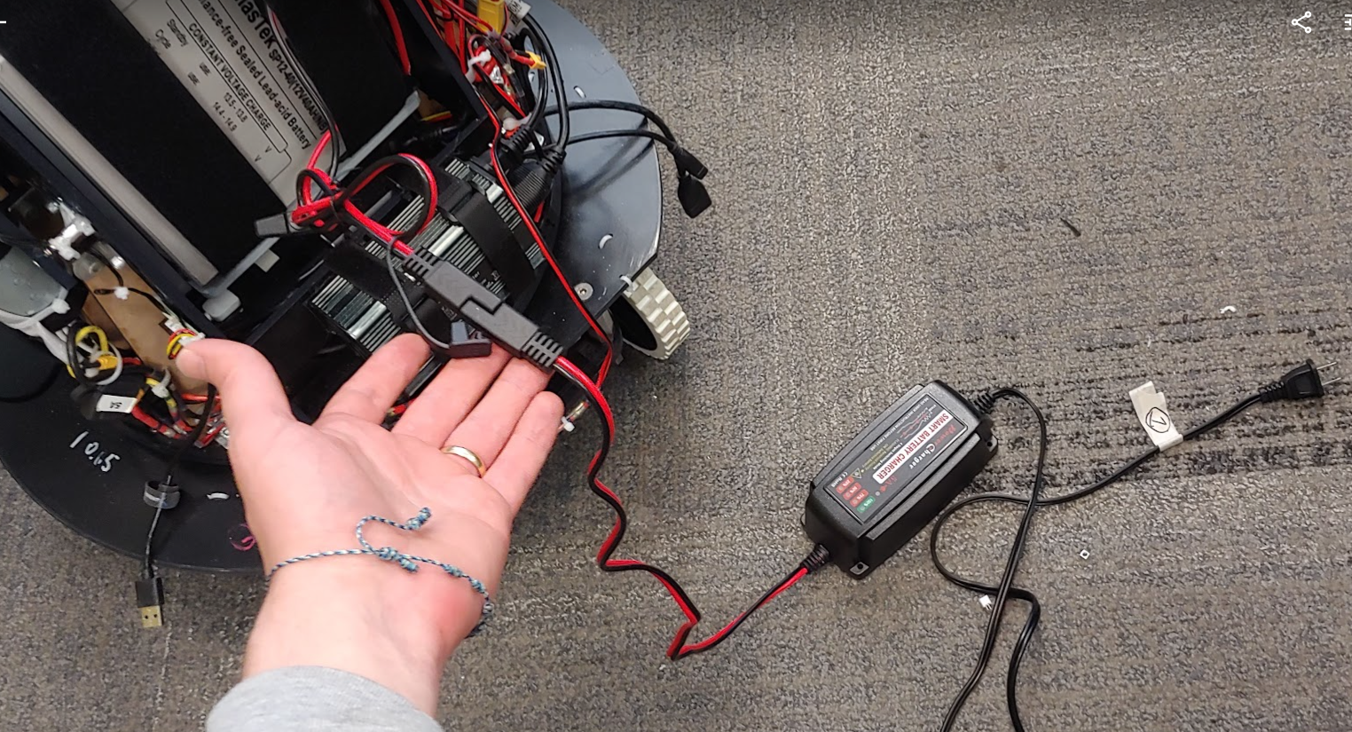
Now connect the charger to AC power.
When you are done charging, place the cap over the charger cable connector and secure the cable under the velcro.
 s
s
Accessing the PC
You can run the robot on battery power or plug it into the wall. For different power configurations see Power Configurations.
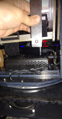
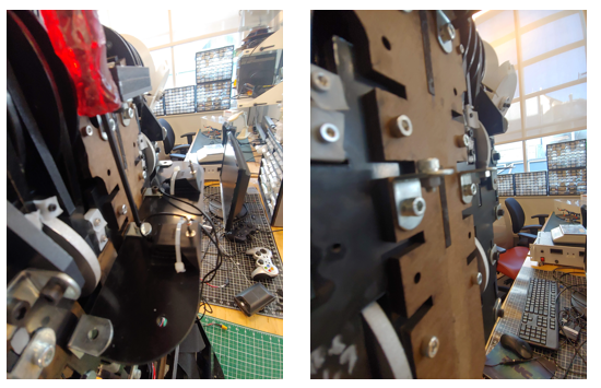
Plug in a monitor to your robot via an HDMI cable to the HDMI port (red in image below) on the back of the robot near the emergency stop button.
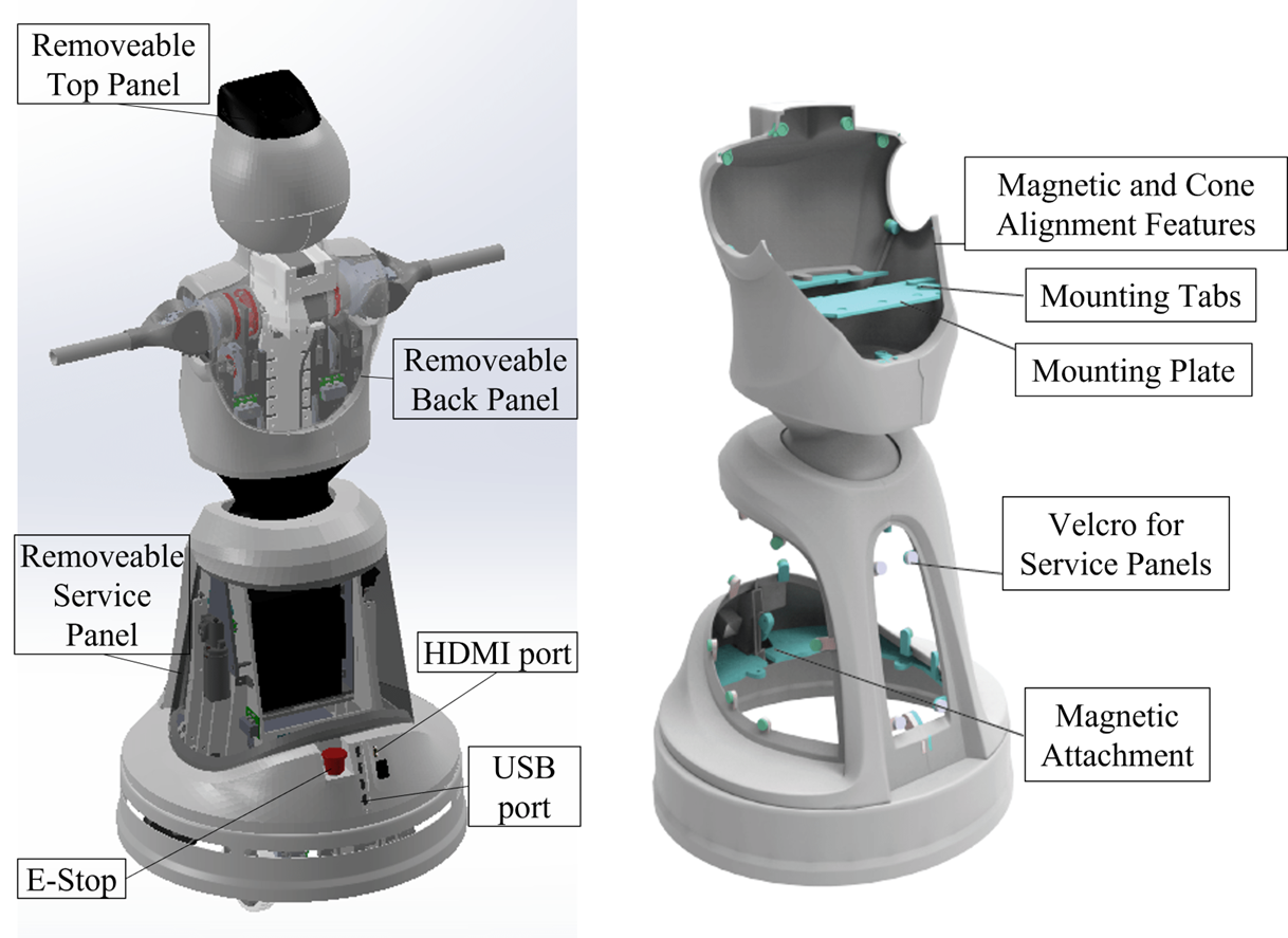
Plug in a usb keyboard and mouse to your robot from the USB hub (blue in image above) on the back of the robot near the emergency stop button.
Turn the main breaker on. Then press the PC on the button for one second to turn the PC on. You should soon see the Qubuntu OS load up and show the Desktop on the monitor. You can set up WiFi and complete any other configurations from here.
With the PC running, you can test the robot's sensors and actuators.
Transportation
Quori was designed to facilitate transportation. This is achieved by the three main modules being able to be separated: the head, torso, and base. The torso and base with the battery and other parts can be stored in the provided pelican case during transportation. The head module ships in a small cardboard box which can be reused. It is recommended that you keep all shipping materials if you plan on transporting Quori over longer distances. The panels should be handled with care during shipping.
See the Assembly Instructions for more information on how to assemble the robot.
Assembly
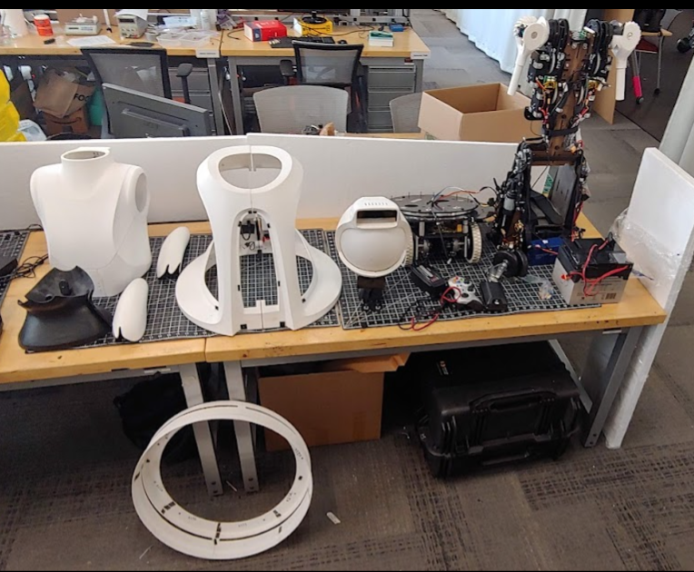
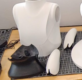
The main modules are the Torso, Head, and Base. The battery and speakers are removable for storage and assembly purposes. Below are all the parts you should have after removing them from the packages. The instructions below will walk you through how to unbox the parts and assemble the robot.
- Panels
- Head Module
- Base Main module
- Base casters
- Battery
- Remote controller
- Battery Charger
- Extra Fuses
- Speakers
- The upper torso module
Materials Needed To Assemble the Robot
The linked items are examples of each item and the exact item is not necessary for assembly.
- 7/16” wrench
- Hex drivers
- M4 drive
- M2.5 driver
- M1.5 driver
- And or a kit like this
- No.2 phillips head driver
- Flat head driver
- 2-3 people
Unpacking
The robot will arrive in multiple packages. The panels are not needed for testing.
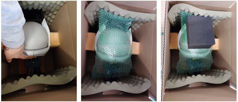
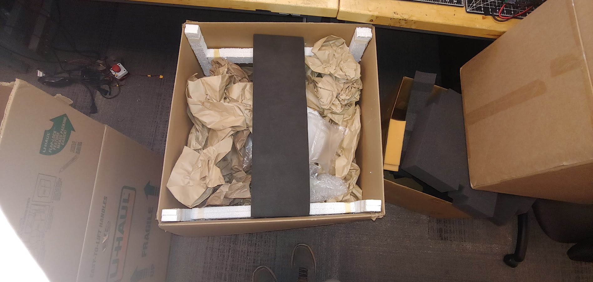
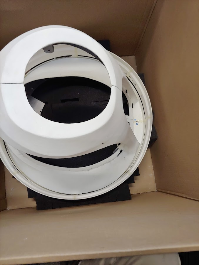
Head Package (1 minute)
The head is packaged along and the box can simply be opened. Take off any packing supplies. A small piece of foam will be between the helmet and the globe at the chin; remove this.
Pelican Case (10 minutes)
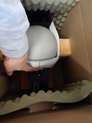
The next package is the pelican 1780 case. Lay the case on its side so the top half can be lifted off (the wheels should be on the ground). Unlatch all of the latches on the case, cut off any zip ties, and lift the top case off. The bottom half should have a foam layer labeled “3”. Take out the battery and the Material Safety Data Sheet (MSDS). Lift the battery by its sides, do not use the single handle. Do not pull on the wires. Take the battery cover (which is anti-static) off and leave it in the case.
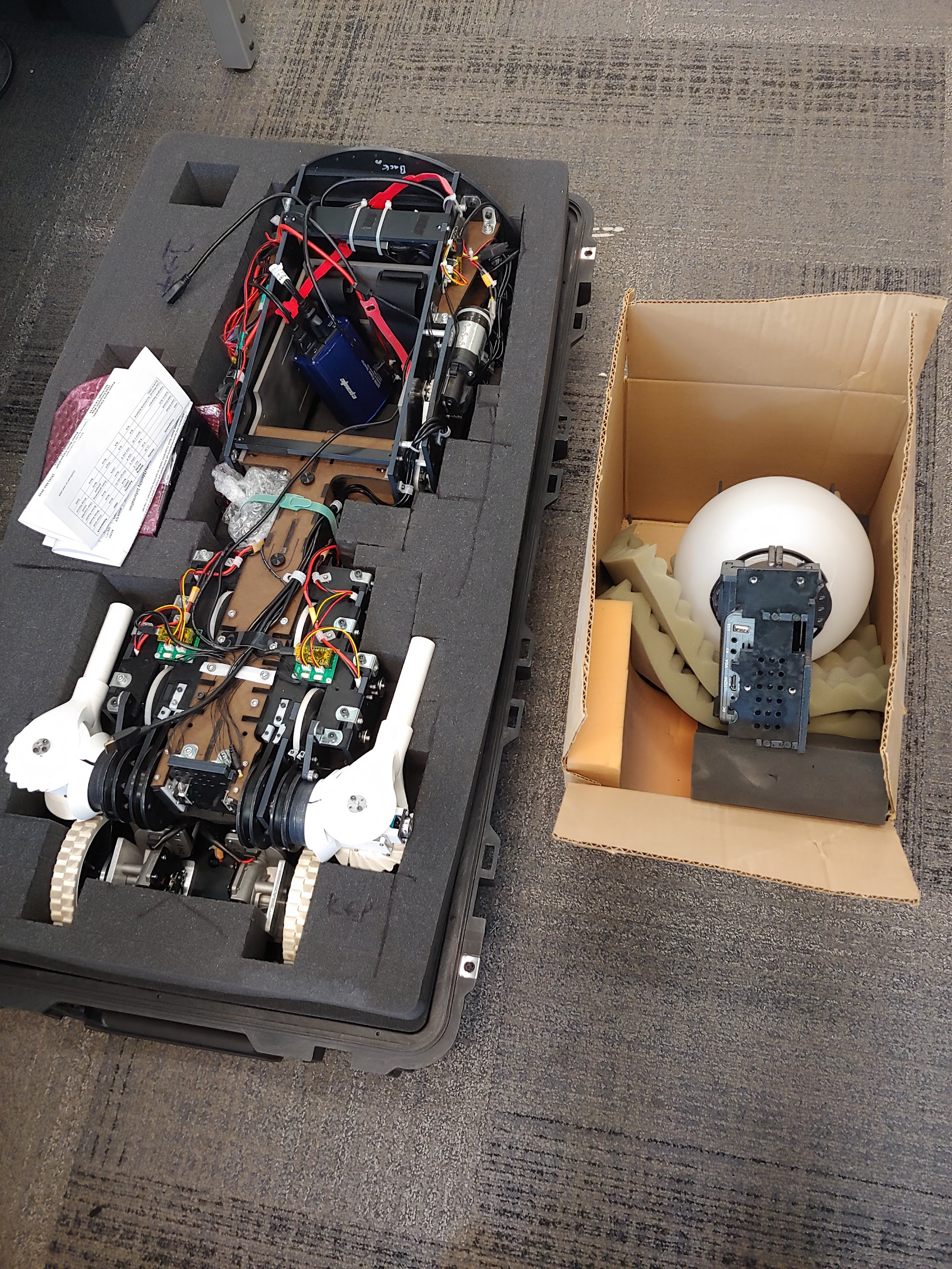
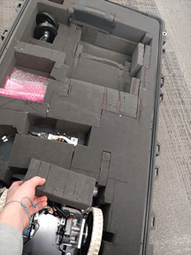
Next, take the layer of foam off of the bottom half of the case to reveal the controller, charger, and speaker.
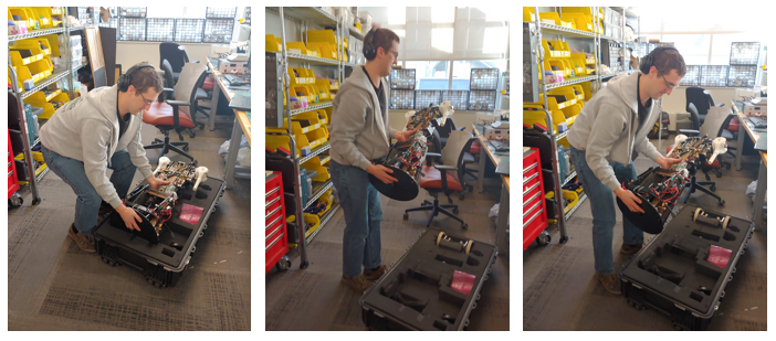
Then remove the torso. You should grab the Torso from the base plate and the waist, See the images below. Two people may be needed.
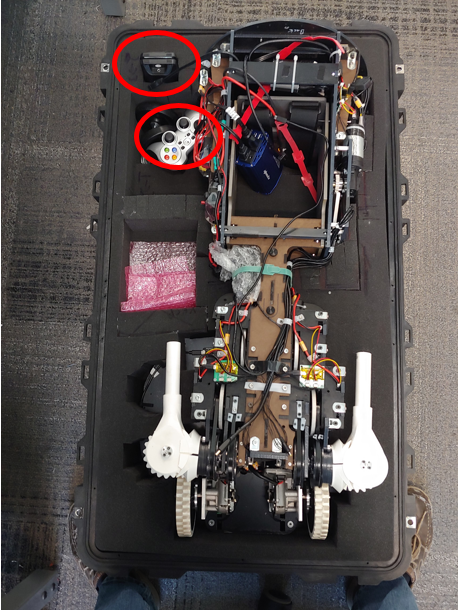
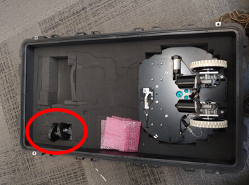
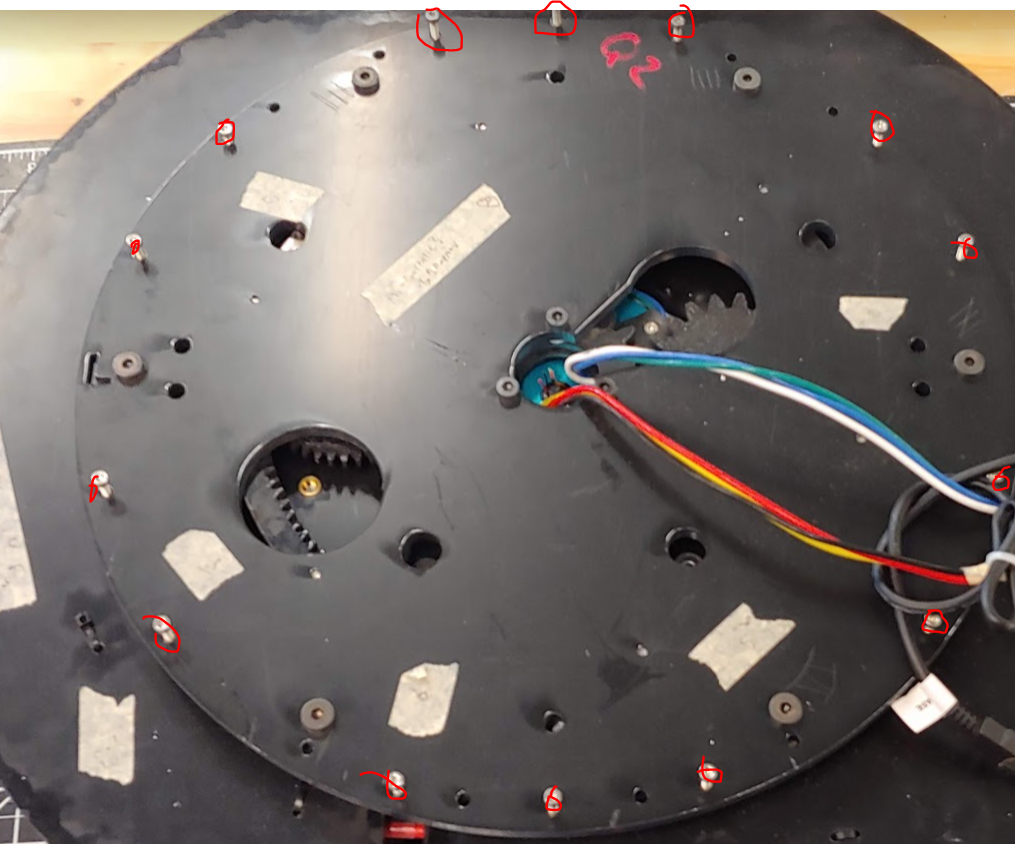
Next, take the next layer of foam out. There is a small block of foam cover the base motors that will also need to be removed. You can then pull the base out of the case. Also, take the casters, circled in red, out of the case.
Prep
Base Prep (5 minutes)
To assemble the base you will first attach the casters. The casters are held on with the 4 screws and nuts each. The screws are taped down and so reattaching should only require a 7/16 wrench. Attach the four nuts with a 7/16 wrench.

Next, remove the 14 M3 fasteners from the base top plate and keep them off to the side. These will be used soon.
Torso Prep(1 minute)
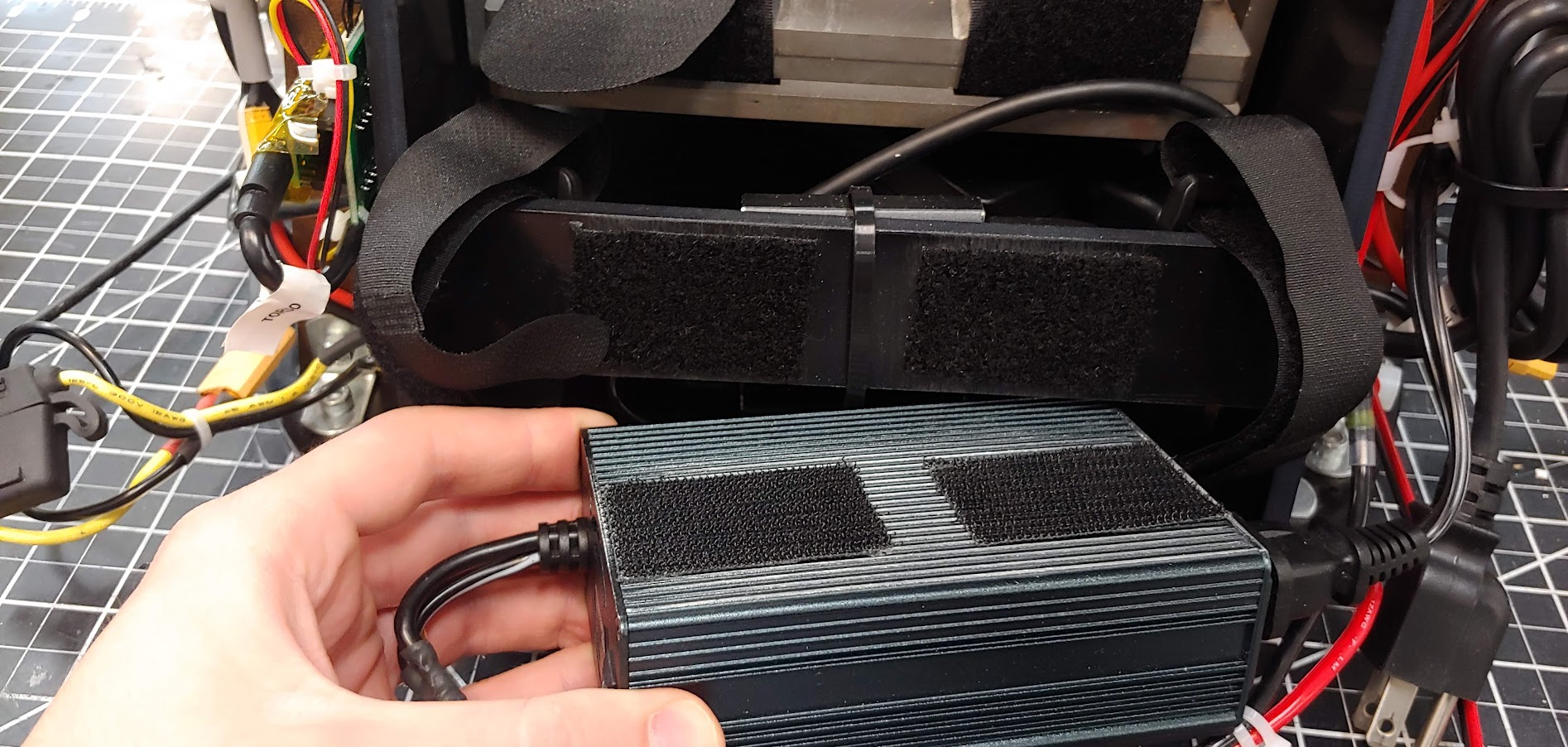
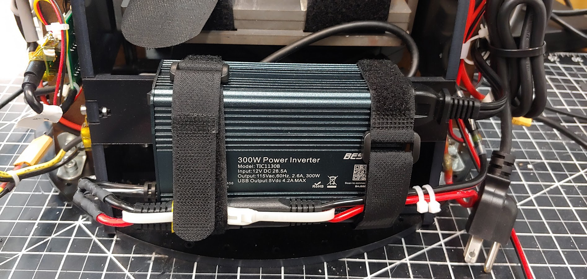
The torso will be mounted to the base. Attach the blue or gray power inverter by lining up the black velcro. Then use the two velcro straps to secure the inverter as shown in the image. You will remove the inverter temporarily later. Make sure the velcro holds the wires near the bottom of the inverter as shown. See video for reference.
ATTENTION: Before using the torso take out the two torso locking M3 bolts. The battery will not fit if these are left in.If you do not use the waist motor remove the 5 Amp fuse near the motor line. Then you can loosen the M3 bolt such that the battery can be placed in it. See video for reference.
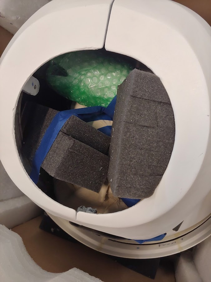
Head Prep (1 minute)
Take out the small piece of foam near the chin of the helmet.
Torso and Base (25 minutes)
Note: You will need two to three people for this stage.Time:
The Torso will now be mounted on the base. There is only one configuration that is proper to mount the base and torso together. Read the next paragraph before trying to mount the base.
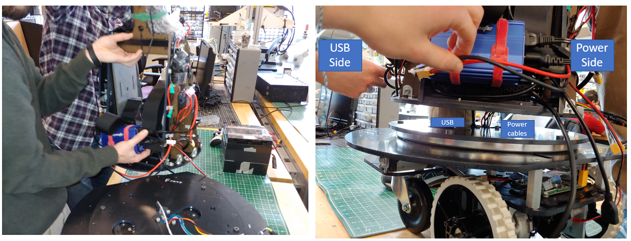
Match the front and back labels of the Torso and Base. Have one or two people lift the Torso by the bottom plate and the waist as shown in the image. You can also hold onto the MDF edge that connects to the steel and the lower ABS cross brace. A third person will guide the usb cable as well as the power cable from the base through the center hole and connecting slot of the Torso and under the computer. The usb cable will go to the left side of the robot, the side with the usb hub. The power cable will go to the right side of the robot. DO NOT pull on these cables as it may damage or sever the cable. If you lifted the PC make sure to reset it so it is laying flat in its bay. If it is not flat the battery bay will collide with it. The torso plate and the base plate should be flush with no gap between them. If there is a gap check all the bolts and holes align well. You may have to apply some pressure to seat the plate over the bolts. Be sure to check that no wires are pinched between the plates. See this video for an example.
With the Torso seated on the base, plug the base’s usb cable into the usb hub.
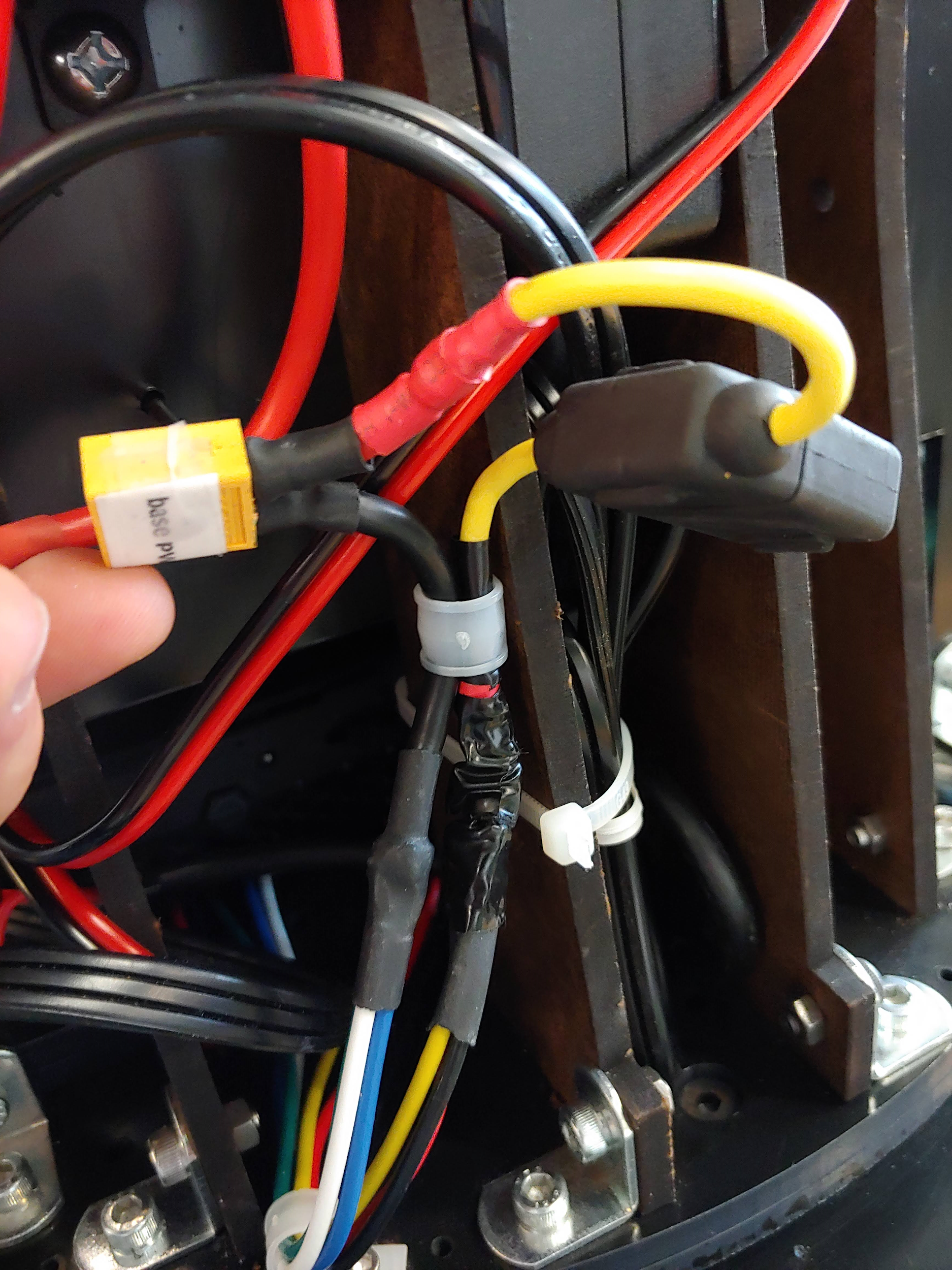
Plug the power into the XT-60 cable labeled “BASE”

Next, attach the wire guides to the usb (the ¼” wire guide) and power cable (the two ⅜” wire guide) using an M2.5 driver. Unscrew the single screw holding the guide down. Insert the guide around the wire and put the screw through both tabs of the guide so that it holds in the wire.
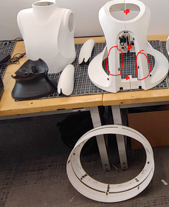
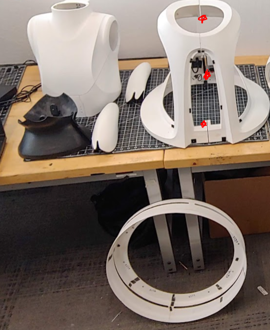
Next install the 14 M3x14mm screws using an m2.5 driver. First unmount the blue power inverter by taking off the two velcro straps, see image. There are 3 screws in the front and back sections and 4 screws on each side section, see image.

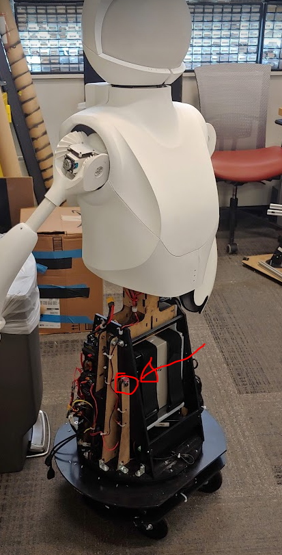
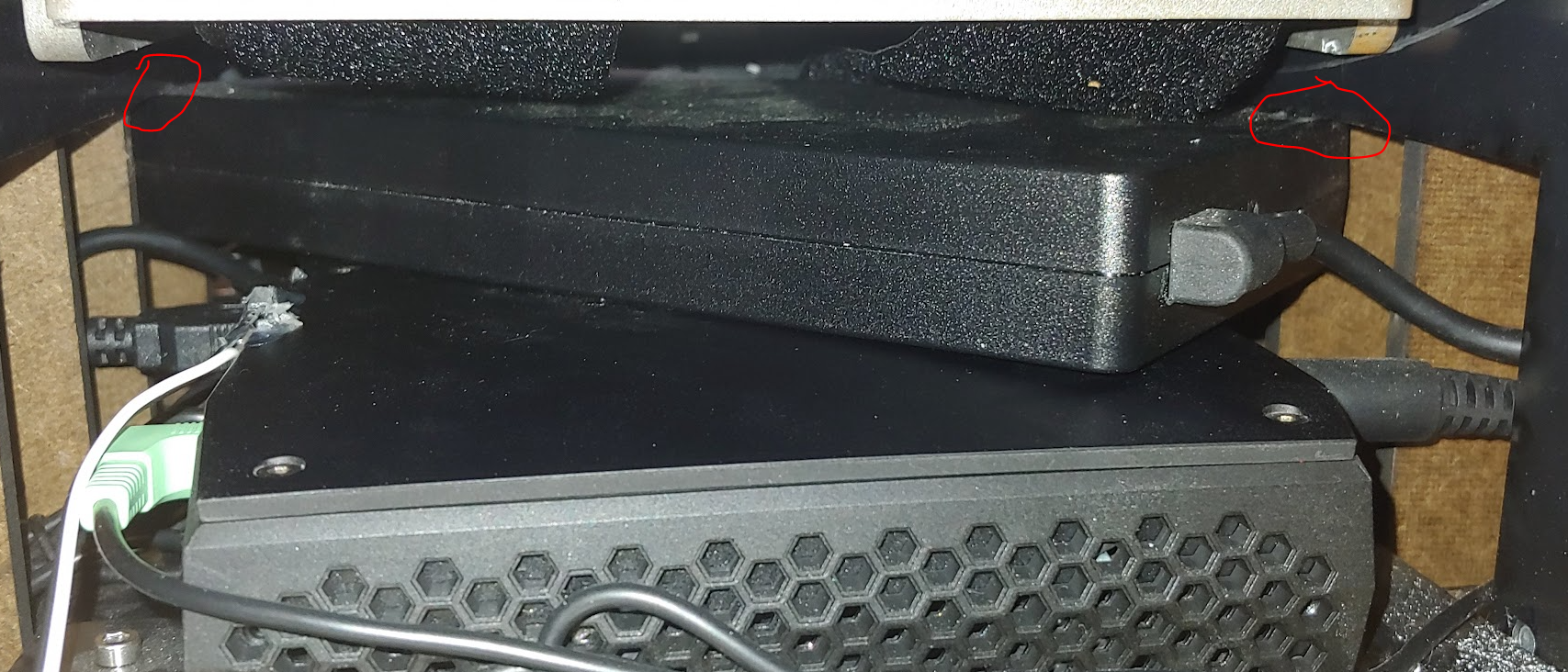
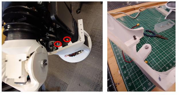
Now verify the PC is sitting flat in its bay. If the PC is no longer flat (due to shipping or other movement) this may lead to collisions when the robot bows forward. The gap, shown in red below, should be greater than 18mm. If the PC power brick is under the ABS side wall edge this is guaranteed, see highlighted in blue in the image below and the two red circles in the right image.
You can now remount the inverter using the velcro straps. See video
Head to Torso (10 minutes)
Place the head onto the torso. Make sure the orientation is correct. The HDMI port should be on the back of the robot with the HDMI cable. Attach the head to the torso using 4 screws.
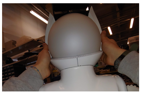
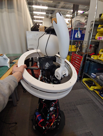
To attach the camera and microphone array you will need to take the helmet panels off of the head module. This panel may already be removed depending on the shipping box.
Take off the middle section using two hands. Pull it directly back to avoid scratching the head

Take off the two lower helmet pieces. These should easily pull apart from the two seems
Next unwrap the camera from the waist by removing the velcro and bubble wrap.
Mount the camera to the sensor carriage using the two screws already found in the camera. Using a phillip’s heaed screwdriver. Before tightening the screws use a straight edge to align the camera as shown in the image below.
Attach the 3 white panels of the helmet first. The lower smaller pieces first, followed by the larger middle section. Be careful to not scratch the globe. See video for reference
Attach the unconnected long micro usb cable from found in the wire guides to the top helmet. You will need to remove the two screws using an m1.5 driver to insert the usb connector into the sensor. Screw the sensor into the helmet as shown. The sensor should push securely against the part, but be careful to not overtighten.

Finally, attach the top helmet piece in the reverse order shown below. Make sure the Camera cable is along the robot’s left side and the microphone cable is along the left side. See video for reference
Speakers (5 minutes)
- To mount the speakers remove the pate mounted near the waist with a thumb screw. Screw the thumbscrew back in to avoid losing it.Take the two screws with nuts off the bracket using an M4 driver and fingers to hold the nut. Be Careful to not drop any parts. Screw the panel UNDER the bracket with the nut and bolt using an M4 driver and fingers to hold the nut. Make sure the panel mounting matches the image, the bracket should be showing above the black panel.
Install the speakers into their mount. They will simply press into the jack on the panel. Each speaker can be mounted to either jack.
Battery (5 minutes)
Before installing the batteries you will need to remove or replace the locking M3 bolts. Note the battery is 24 pounds. A video link is provided at the end of these instructions.
ATTENTION: Before using the torso take out the two torso locking M3 bolts. The battery will not fit if these are left in.If you do not use the waist motor remove the 5 Amp fuse near the motor line. Then you can loosen the M3 bolt such that the battery can be placed in it. See video for reference, note the two locations might be mirrored for each robot.
ATTENTION: Make sure the main breaker is OFF before starting this step.

Unwrap the two velcro straps.
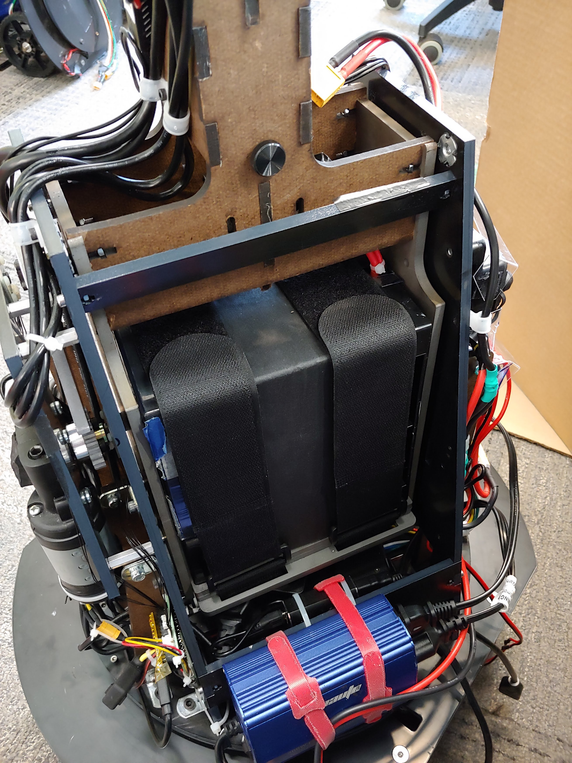
Make sure the two steel counter mass plates are centered on the bottom steel plate and fit tightly against the side walls. The robot may struggle to move the waist If the counter plates are not centered. The front and back edges of the steel plates should be flush with the slot in the bottom plate that the velcro straps enter into, i.e the two plates should be be touching the velcro straps.
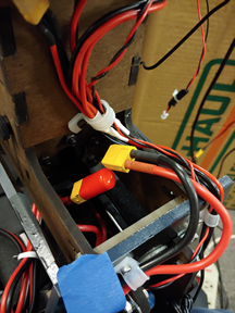
Next, slide the battery into the back of the robot and into the battery bay such that the battery cables are in the upper right corner of the robot’s battery bay. Be sure that the two counter mass plates do not shift. This is easiest to do from the back of the robot. The battery power cable will need to be positioned around the waist hex shaft inorder for the plug to be connected to the rest of the robot.
Then strap the battery into the bay with the two velcro straps. Be sure to secure the charging cable to the battery with the velcro straps.
Panels
Open the large box with the panels so that the shipping label is facing up.
Carefully remove the packing material from around the panels
Remove the plack service panels from the lower torso
You should now be able to remove the bubble wrapped panels from the inside of the lower torso. Parts to remove are shown below: the black waist front and the black waist back, and the 4 chest pieces, and the two lower arms.
Then carefully pull out the lower torso from the skirt (the fit is tight). Use the vertical beams (circled in red) in the front to help support the panels as you remove the part
The remove the laser scanner skirt from the box
Then remove the three thumb screws (red stars in the image below) that hold the two halves of the lower torso together. Do not lose these screws.
Waist (6 minutes)
- Take off the four thumb screws near the waist, see image
Note that the two pieces are not interchangeable and the one labeled front should be on the same side of the robot as the speakers. The front piece is the one with male (protruding) alignment cones. Attach the waist to the torso using the thumbscrews. Put the thumbscrews into the waist tabs and then align the waist and then screw the thumbscrews hand tight. Be careful to not catch any wires under the plastic part.
Lower Torso (10 minutes)
Place the skirt on the base. You may need to position the arms so the skirt can move around them.

Place the right lower torso panel next to the robot (with the usb and HDMI cables) Next, plug in the USB and HDMI cables into the extensions.
Next attach the panel, using the thumbscrew, to the top of the torso's black ABS plate on the robot, see below images. Place the thumbscrew in the lower torso’s mounting tab before mounting the part.
Check that the cables do not hang below the panel as it can get caught if so.
Repeat for the left lower torso part, first connecting the E-Stop wire and then mounting the panel to the robot

Check that the cables do not hang below the panel as it can get caught if so.
Next fasten the remaining three thumb screws that connect the left and right lower torso panels. There is one in the lower front, one at the lower back, and one at the upper back. The thumbscrew should enter the left lower torso tabs and thread into the right lower torso tabs. The three panel-to-panel thumbscrew locations are shown at the first part of this video and the left and right panel-to-robot thumbscrew locations are shown at the end.
Upper Torso (10 minutes)
-
Move the right arm outward before attaching the left panel. Unscrew the M3 thumbscrew by hand. Be careful that the screw does not fall into the robot. Place the screw on the torso panel first and then moving the chest panel into place. Screw the screw into mounting panel as shown in the video. The right panel mounting tab should be below the torso mounting panel as shown in the image below.

-
Move the left arm outward before attaching the left panel. Unscrew the M3 thumbscrew by hand. Be careful that the screw does not fall into the robot. Place the screw on the torso panel first and then moving the chest panel into place. Screw the screw into the mounting panel as shown in the video. The left panel mounting tab should be below the torso mounting panel as shown in the image below. below the torso mounting panel as shown in the image below.
-
Attach the low voltage sensor wire to the right panel. See the start of this video for reference.
-
Follow the images below from right to left. The front panel should only be placed with the helmet off or at least the lower two chin pieces of the helmet. Magnets will hold this part in place to the left and right chest pieces. See video for reference

-
The back chest panel should easily slide into the three mounted pieces and be held in place with its magnets. Make sure the microphone usb cable is to the left and fits in the notch on the left side of the panel and the camera usb cable fits in the notch on the right side of the panel. See video for reference
Helmet (5 minutes)
Attach the 3 lower panels of the helmet first. The lower smaller chin pieces first, followed by the larger middle section. Be careful to not scratch the globe.


Finally, attach the top helmet piece in the reverse order shown below. Make sure the Camera cable is along the robot’s left side and the microphone cable is along the left side. See video for reference

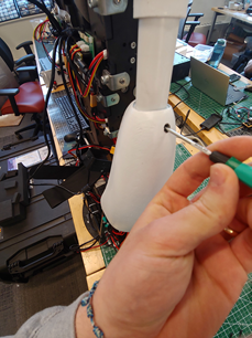
Lower Arms (2 minutes)
- You can attach the lower arms by tightening the set screw in the arm with a m1.5 driver. You should only need to turn the set screw 3-5 revolutions. Do not overtighten the set screw. The arms should be installed so the thumbs (the smaller protrusion on the hand) faces forward. This can be repositioned as desired. See video for reference

Service Panels
The back service panel uses velcro to attach to the lower torso panels. Start with the robot’s right side and align the velcro strips. Work your way to the robot’s right side, aligning the velcro along the way. The bottom of the robot’s right side will have a gap large enough to fit a finger through. This is used to remove the panel for servicing. See video for assistance in assembly

The front service panel attaches to the lower torso panels with velcro.
Disassembly
Be sure to turn off the main ON/OFF relay switch before maintaining the system. Note that most of the panels are held in place using magnets. Some of the connections use screws.
Make sure all power is off and not connected when servicing the robot. Turning off the main ON/OFF relay switch will do this. You may also want to unplug the battery. When you unplug the battery from the robot be sure to place the connector cover over the battery connector.

Panels
Helmet (2 minutes)
-
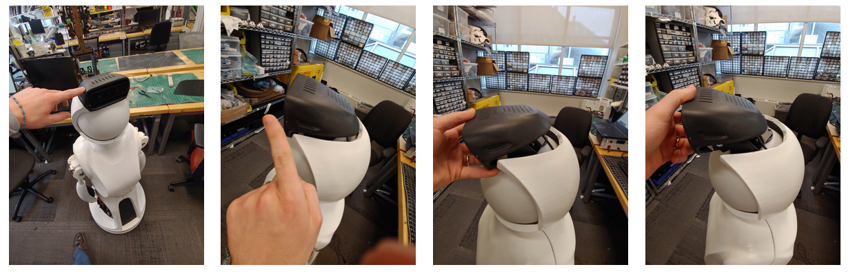
Take off the top sensor cover. Pull out towards the front of the robot and rotate its back forward as shown in the images. You may want to unplug the microusb from the audio sensor or unscrew it from the helmet using an m1.5 screw driver.

-
Take off the middle section using two hands. Pull it directly back to avoid scratching the head
-
Take off the two lower helmet pieces. These should easily pull apart from the two seems

Chest (2 minutes)
-
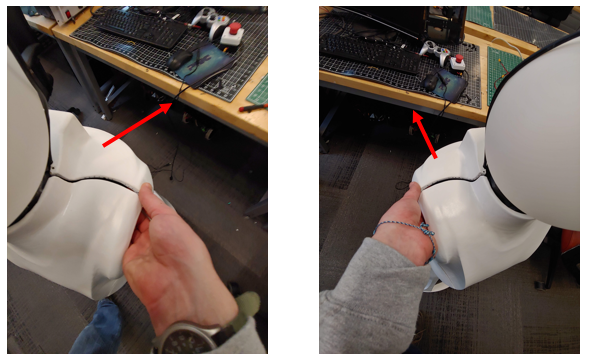
Separate the front and back chest pieces using two hands. See images. Then pull off the back panel. Be careful to not let the front panel fall off.
-
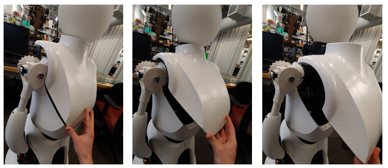
Lift the front panel up and out slightly. Then rotate the bottom of the panel outward. Finally pull the panel off the robot. See three images.
-
Move the left arm outward before removing the left panel. Unscrew the left panel by hand from the thumbscrews. Be Careful that the screws do not fall into the robot. Screw the thumb screws into the panel when done.
-
Unplug the low voltage LED cable. Do reverse of this video
-
Move the right arm outward before removing the right panel. Unscrew the right panel by hand from the thumbscrews. Be Careful that the screws do not fall into the robot. Screw the thumb screws into the panel when done.

Lower Torso (15 minutes)
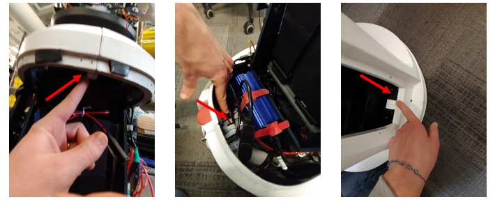
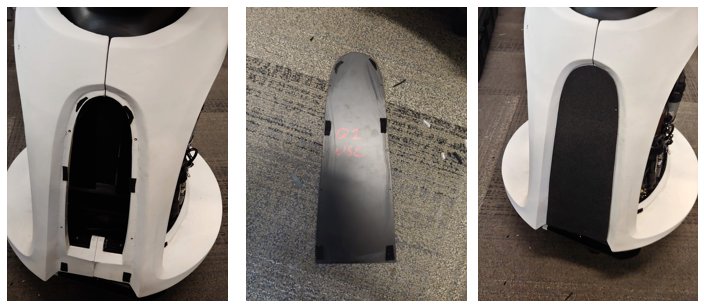
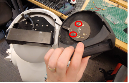
- Take off the front and back service panels by pulling the panel off. The images below show the locations that will allow a finger to start separating the service panel from its velcro attachment. The bottom right side for the back service panel and the bottom for the front service panel.

-
Unscrew the 3 thumb screws that connect the left and right lower torso panels. There is one in the lower front, one at the lower back, and one at the upper back.

-
Unplug the HDMI, usb, and emergency stop wires from the panel

-
Unscrew the left thumb screw that holds the lower torso to the robot structure. Be Careful not to drop the thumbscrew. Repeat the same process on the other side. Reinstall the thumbscrew in the hole after the panels are removed to prevent losing them. Do not screw the thumbscrew past the insert as this could block the robot bowing motion if the robot is run without the panels.
-
Pull off each side. Note that a magnet pulls the two lower halves together at the front top and the base skirt also connects to both sides using magnets.

-
Take off the base skirt. You will need to lift one arm up and have the other arm down to do this unless you take off the lower arms
-
Remove the lower arms by loosening the set screw in the arm with a m1.5 driver. You should only need to turn the set screw 1-3 revolutions. Do not remove the set screw.
Waist (3 minutes)
-
Take off each waist by unscrewing the top and bottom thumb screws, see images for examples. Note that the two pieces are not interchangeable and the one labeled front should be on the same side of the robot as the speakers. The front piece is the one with male (protruding) alignment cones.Be sure to put the thumb screws onto the robot to prevent losing them.


Head (15 minutes)
Make sure all power is off and not connected to the head module. Turning off the main ON/OFF relay switch will do this.
-
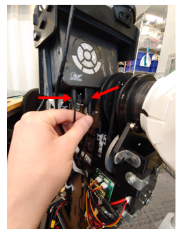
Unplug the HDMI, and power cable from the bottom of the projector.

-
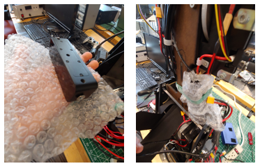
Disconnect the camera. For the camera you can either take the camera off its mount or unplug the camera usb cable and unrouting it from its two guides. We recommend removing the camera. To remove the camera from its mount use a Phillips head screwdriver two take the two screws off holding it to its mount. Install the screws into the camera to avoid losing them, see image. You should then store the camera in the torso right side as shown in the below image using a velcro strap. Wrap the camera with bubble wrap to help protect it.


-
Either carefully place the top head panel and microphone off to the side, or remove the microphone usb cable and allow it to hang next to the camera.
-
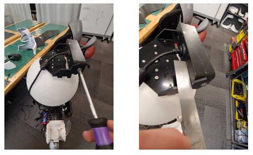
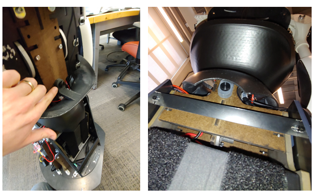
You need to pull out the speakers from their mount to remove the head. See images of the four screws and the unmounted speaker. You may want to take the torso mounting plate off before removing the head. See next step if so.
-
You need to take the torso mounting plate off to remove the head. Take the two screws with nuts off the panel using an M4 driver and fingers to hold the nut. Be Careful to not drop any parts. Screw the nut and bolt together on the bracket after removal. Mount the plate as shown in the imaging using the front waist’s top thumb screw.


- Remove the 4 screws holding the head module to the torso using an m4 driver, see next step before proceeding. Only remove the four black screws, they should be vertical and going into the black ABS peices, that is, do not take out the screws going into the MDF structure. Screw the 4 bolts into the head plate to avoid losing the screws.

- Remove the 4 screws holding the head module to the torso using an m4 driver, see next step before proceeding. Only remove the four black screws, they should be vertical and going into the black ABS peices, that is, do not take out the screws going into the MDF structure. Screw the 4 bolts into the head plate to avoid losing the screws.
Base and Torso (20 minutes)
Make sure all power is off and not connected to the base module. Turning off the main ON/OFF relay switch will do this. You will need three people to do this.
Before attempting to remove the torso from the base you will need to unplug the power cable and the usb cable as well as 14 screws using an m2.5 driver. It is best to have three people to help lift the robot and guide the cables through. The instructions below will detail this.
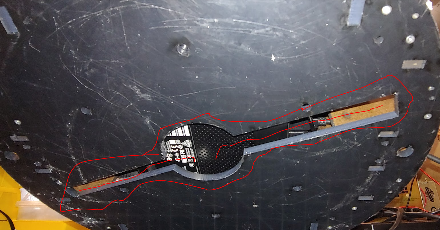
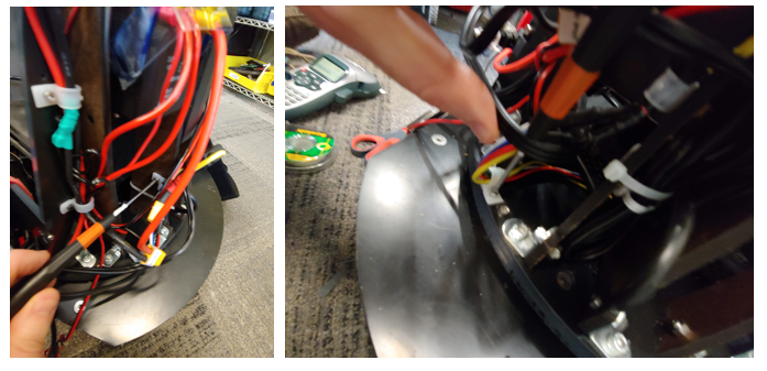
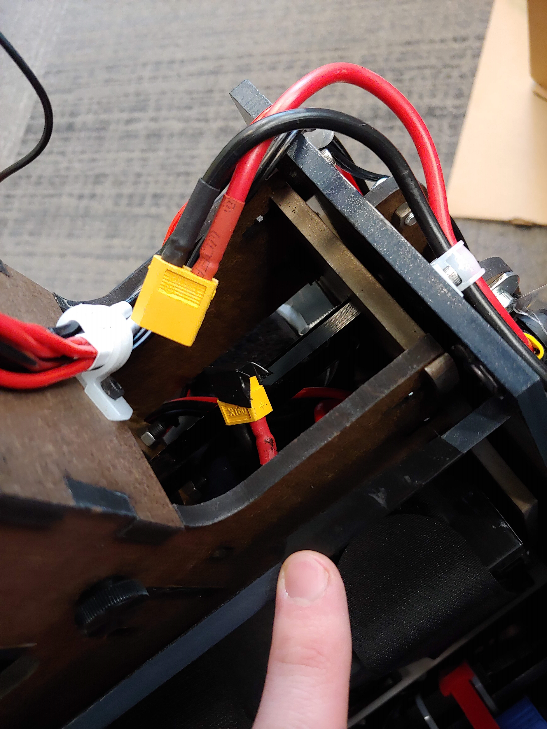
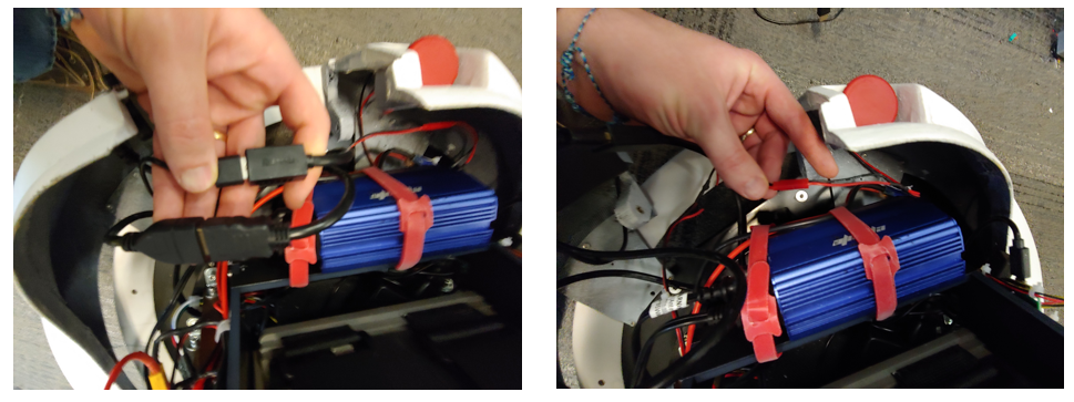
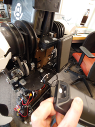
You may want to take the battery out of the robot to make it easier to lift the robot. Again, make sure the main relay is off before doing this. You will unplug the xt-60 connector. You should cover the battery xt-60 connect an XT-60 cap as a safety precaution. Then move the wire under and out of the structure, see image. Then, take off the two velcro straps. Then carefully pull the battery out towards the back of the robot. Note the battery weighs about 24 pounds. You may want to insert two M3x60 bolts into the waist to lock it in place. Do the reverse of the following:
Before installing the batteries you will need to remove or replace the locking M3 bolts. Note the battery is 24 pounds. A video link is provided at the end of these instructions.
ATTENTION: Before using the torso take out the two torso locking M3 bolts. The battery will not fit if these are left in.If you do not use the waist motor remove the 5 Amp fuse near the motor line. Then you can loosen the M3 bolt such that the battery can be placed in it. See video for reference, note the two locations might be mirrored for each robot.
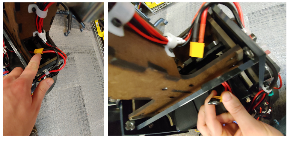
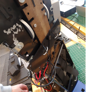
First unplug the base power plug located on the robot’s right side. Then, remove the wires from the guides by taking off the two guides using an m2.5 driver, see images. Reattach the guides sans power wire to prevent losing the part. Next unplug the base serial cable from the usb hub on the left side of the robot. Then take off the wire guide using an m2.5 driver.


Next take the 14 screws off using an m2.5 driver. First unmount the blue power inverter by taking off the two velcro straps, see image. There are 3 screws in the front and back sections and 4 screws on each side section, see image. screw these 14 screws into the base holes to prevent losing them. Leave the inverter velcro straps hanging where they were.
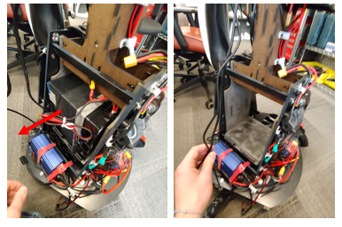
You will need at least two people for this step. Next, you may need to lift the PC to help guide the power and usb cable through the mounting hole/slots. Then have two people lifting from the lower back brace and the waist of the robot while a third person guides the usb and power cable under the torso module and out, see image.

Screw the 14 M3 screws into the base to avoid losing them.
For storage into the pelican case you will need to remove the casters. The casters are held on with the 4 screws and nuts each. The screws are taped down and so removal and reattaching should only require a 7/16 wrench. Remove the four nuts with a 7/16 wrench and then remove the caster. Reattach the 4 nuts to the screws hand tight to prevent losing them.
If you are shipping the torso unit please consider installing the two M3x60 bolts that lock the battery bay inplace. This will help reduce stress on the waist transmission during shipping.
Testing
The following should be verified after your first assembly to verify no parts were damaged during shipping. You can also use this as a basic test if something is not working.
Joint Functions
You will need to plug the robot into power and use the e-stop. Be sure the robot is not able to collide with any objects before starting.
Arms and Waist
-
Launch the holonomic controller:
roslaunch quori_controller quori_control_holo.launch -
Launch the rqt_trajectory_controller:
/opt/ros/noetic/lib/rqt_joint_trajectory_controller/rqt_joint_trajectory_controllerAs a sanity check before you enable control in
rqtensure that the arms and waist are reading valid positions (values are within the range of the slider and respond to slight movement) -
Enable control of the joints by pressing the red button in
rqt. -
Use the slider to move each joint to its extreme position and back to a resting position
-
Close out of
rqtand any ROS nodes
Base
-
Launch the holonomic controller:
roslaunch quori_controller quori_control_holo.launch -
Launch the teleop node:
roslaunch quori_teleop quori_teleop.launchMake sure the USB remote receiver is plugged into Quori (the USB hub on the Quori panel is the recommended location)
-
Control the base: hold the left bumper LB and use the thumbsticks to move the robot. See teleop repo for more information
Testing Sensing Functions
Camera
-
Launch the camera node:
roslaunch astra_ros default.launch -
Test that the images are streaming with the following commands. The depth image will be difficult to see pixels depending on what the camera is able to see.
rosrun image_view image_view image:=/astra_ros/devices/default/color/image_colorThen close out of this node and run
rosrun image_view image_view image:=/astra_ros/devices/default/depth/image
LIDAR
-
Launch the laser scanner node
roslaunch rplidar_ros rplidar.launchIf you are getting an error try unplugging and replugging in the lidar usb cable. You can also see the Troubleshooting section
-
Launch the terminal client
rosrun rplidar_ros rplidarNodeClientIf you see numbers streaming on the terminal then the sensor is working
Microphone
-
Launch the sensor’s node(s)
roslaunch respeaker_ros sample_respeaker.launch -
Echo a data topic
rostopic echo /sound_directionIf you see data echoing as you make noise around the head of the robot then the sensor is working
Face
We will test that the calibration image is properly centered. You will need a remote PC with x11 forwarding. ssh into Quori and then do the following:
roslaunch quori_face calibrate.launch
You should see a crosshair centered on the robot’s face. You can update hardware calibration with new dx and dy values by using the dynamic reconfigure window that should have appeared on the remote PC (via x11 forwarding). You should not need to update the dx and dy values.
Navigation Basics
Quori can navigate a map using ROS’s navigation stack. Use a remote laptop to set up a ROS network. The following launch files will get you started.
roslaunch quori_launch mapping.launch
roslaunch quori_controller quori_control_holo.launch
roslaunch quori_nav move_base.launch # if autonomous otherwise use telop
Then run RViz on a remote desktop that is on the same ROS network.
- Load map, laser scanner, and robot model into Rviz
- Use 2d Nav in rviz to move around map
Software
Overview
This sections provides links to the software repositories for Quori as well as information about the computer and microcontrollers. For detailed information about using Quori with ROS please visit Quori’s ROS wiki page at: http://wiki.ros.org/Robots/Quori.
Quori has two main software categories: (1) low-to-mid-level, including core control of each module (actuation and sensing); and (2) high-level social interaction software (animation and dialog tools).
ROS is used for mid-level control of modules. PC usage is in parallel with the microcontrollers that control motor position, speed, measurements, safety, etc.
Repositories
The following are links to the software repositories that are already installed on your Quori robot.
ROS packages for Quori
-
https://github.com/Quori-Robot/quori_ros/tree/master/src/quori_face
-
https://github.com/Quori-Robot/quori_ros/tree/master/src/quori_controller
-
https://github.com/Quori-Robot/quori_ros/tree/master/src/quori_launch
Linux OS for Quori
https://github.com/Quori-Robot/Qubuntu
Embedded Code for Microcontrollers
https://github.com/Quori-Robot/quori_embedded
Getting Started
Running from the Robot
From a Linux PC session with Xorg:
ssh -X quori<robot number>@<robot address>
roscore &!
Running from a PC
You need a ROS 1 "noetic" installation.
Make sure to source ROS 1 before continuing:
source /opt/ros/noetic/setup.bash
The quori_ros repository is a ROS 1 workspace, that can be built with catkin_make.
git clone https://github.com/Quori-Robot/quori_ros.git
cd quori_ros
git submodule init
catkin_make
. ./devel/setup.sh
Then run roscore with the appropriate ROS_IP and ROS_MASTER_URI environment variables
on both the PC and the robot.
Starting the Demo configuration
Then you can run the demo launch file:
roslaunch quori_launch demo.launch
It launches:
- the navigation stack
- the mapping and the laser publishers
- the controller stack for Quori in holonomic mode
Other launch files are available in the quori_launch package:
-
launch the laser stack (including filtration) and SLAM system.
roslaunch quori_launch mapping.launch -
Publishes the laser's static transform.
roslaunch quori_launch tf_base_laser.launch -
Publishes the laser filtration stack (used by mapping.launch).
roslaunch quori_launch filtered_laser.launch
Robot Description
The package quori_description
provides URDFs for Quori and the RAMSIS base, as well as a URDF for the combination of the two.
Quori Standalone URDF (urdf/quori_standalone.xacro)
This URDF file allows one to use the Quori robot without the RAMSIS base attached.
Joints
waist_pitch(revolute) - The waist joint.r_shoulder_pitch(revolute) - The first joint of the right arm.r_shoulder_roll(revolute) - The second joint of the right arm.l_shoulder_pitch(revolute) - The first joint of the left arm.l_shoulder_roll(revolute) - The second joint of the left arm.
Notable Links
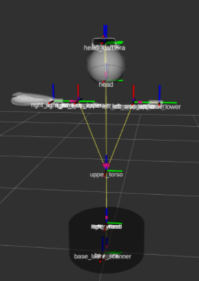
quori/base_link- The root of the Quori kinematic tree (Note: This is not the root when using the RAMSIS base with Quori)quori/head_camera- The frame for the Orbbec Astra Mini.quori/head_mic- The frame for the head-mounted ReSpeaker microphone array.
RAMSIS Standalone URDF (urdf/ramsis_standalone.xacro)
This URDF file allows one to use the RAMSIS holonomic base without Quori attached.
Joints
l_wheel(continuous) - The left wheel joint.r_wheel(continuous) - The right wheel joint.turret(continuous) - The rotational joint for the mounting plate on top of the RAMSIS base (typically occupied by Quori).
Notable Links
ramsis/base_link- The root of the RAMSIS kinematic tree (Note: This is the root when using both Quori and the RAMSIS base).ramsis/base_laser_scanner- The frame for the RAMSIS-mounted 2D LIDAR.
Quori + RAMSIS URDF (urdf/quori.xacro)
This URDF contains all joints and links from both quori_standalone.xacro and ramsis_standalone.xacro. This URDF file should be used in the default configuration where Quori is mounted on top of the RAMSIS base.
Face
The package quori_face
accepts an image and displays it on the Quori face. The image is treated as containing radial pixels along the polar and azimuthal axes of the spherical face.
Calibration
To calibrate, run roslaunch quori_face calibrate.launch. This will spawn quori_face_node with a grid image and a dynamic_reconfigure user interface for adjusting the calibration. At exit, the new calibration will be written to quori_face/config/params.yaml.
Usage
To use, run roslaunch quori_face quori_face.launch.
Parameters
Transform Parameters
These parameter names directly correspond to the paper "LOW COST OPTICAL MECHANICAL SYSTEM FOR HUMAN ROBOT INTERACTION" (IMECE2018-87885) on the face projection transform algorithm.
~transform/R: double(default:4.0) - Radius of the spherical head.~transform/r_m: double(default:1.5) - Radius of the mirror.~transform/r_o: double(default:2.0) - Radius of the base circle at the bottom of the head.~transform/h: double(default:1.0) - Distance from the center of projection to the bottom of the head.~transform/L: double(default:8.4476252817457738) - The distance between the projection center and the intersection of the projection axis and the sphere.~transform/epsilon: double(default:0.059068559067049511) - The angle between the axis of roation of the circle and the intersection of the projection axis and the sphere.~transform/delta/x: double(default:-2.9) - X-axis projector installation error.~transform/delta/y: double(default:-1.6) - Y-axis projector installation error.~transform/screen_size/x: uint32(default:1920) - Width of the projector screen in pixels.~transform/screen_size/y: uint32(default:1080) - Height of the projector screen in pixels.
Lookup Table Parameters
quori_face aggressively caches the expensive transform algorithm into a lookup table.
~lookup_table_resolution/x: uint32(default:2048) - Width of the transform lookup table in pixels.~lookup_table_resolution/y: uint32(default:2048) - Height of the transform lookup table in pixels.
Image Parameters
The input image must be of fixed width and height during the execution of quori_face_node. If the received image is of a different size, it is resized before being transform. For optimal performance, this value should match the expected input image resolution.
~image_resolution/x: uint32(default:1280) - Expected width of received images for display.~image_resolution/y: uint32(default:720) - Expected height of received images for display.
Spherical Mapping Parameters
Quori may optionally be configured with a helmet. We can adjust the spherical region mapped to the input image by adjusting the min and max coordinates.
~center/theta: double(default:1280) - Central polar value (that corresponds to the center of the image), in radians, to map.~center/psi: double(default:720) - Central azimuthal value (that corresponds to the center of the image), in radians, to map.~min/theta: double(default:-PI * 0.45) - Minimum polar value, in radians, to map.~min/psi: double(default:-PI * 0.5) - Minimum azimuthal value, in radians, to map.~max/theta: double(default:PI * 0.45) - Maximum polar value, in radians, to map.~max/psi: double(default:PI * 0.5) - Maximum azimuthal value, in radians, to map.
Dynamic Reconfigure Options
quori_face allows certain ROS parameters to be adjusted on-the-fly for easy calibration.
dx: double- The~transform/delta/xvalue (see above).dy: double- The~transform/delta/yvalue (see above).center_theta: double- The~center/thetavalue (see above).center_psi: double- The~center/psivalue (see above).min_theta: double- The~min/thetavalue (see above).min_psi: double- The~min/psivalue (see above).max_theta: double- The~max/thetavalue (see above).max_psi: double- The~max/psivalue (see above).
Subscribed Topics
image: sensor_msgs/Image- The image to display on the face. The image is treated as being composed of radial pixels. For optimal performance, the image should match the configured~image_resolutionand be BGR8 encoded.
Navigation
The package quori_nav
contains launch and configuration files for the ROS navigation stack.
Launch Files
roslaunch quori_nav move_base.launch
Launches move_base with the planner configuration defined in quori_nav/config/.
Configuration Files
config/base_local_planner_params.yaml
Contains ROS parameters for the TrajectoryPlannerROS move_base plugin.
config/costmap_common_params.yaml
Contains common costmap parameters.
config/dwa_local_planner_params.yaml
Contains ROS parameters for the DWAPlannerROS move_base plugin.
config/global_costmap_params.yaml
Contains global costmap parameters.
config/local_costmap_params.yaml
Contains local costmap parameters.
Teleoperation
quori_teleop
allows teleoperation of Quori using an Xbox or Playstation style controller.
Controller Mappings
Left Arm Control (Hold Left Trigger)
l_shoulder_pitch- Left Thumb Stick (Y axis)l_shoulder_roll- Left Thumb Stick (X axis)
Hold A for "fast" mode, which doubles the movement speed.
Right Arm Control (Hold Right Trigger)
r_shoulder_pitch- Right Thumb Stick (Y axis)r_shoulder_roll- Right Thumb Stick (X axis)
Hold A for "fast" mode, which doubles the movement speed.
Base Control (Hold Left Bumper)
Move the holonomic ramsis base.
- Linear X - Left Thumb Stick (Y axis)
- Linear Y - Left Thumb Stick (X axis)
- Angular Z - Right Thumb Stick (X axis)
Waise Hinge Control (Hold Right Bumper)
waste_pitch- Left Thumb Stick (Y axis)
Subscribed Topics
/joint_states- Used for joint position feedback/joy- Joystick input from the ROSjoynode.
Published Topics
/quori/base_controller/cmd_vel- The commanded velocity for the ramsis base/quori/joint_trajectory_controller/command- Joint trajectory commands for Quori's joints.
System
Quori v1 ships with a nuc8i7hvk: Intel© CoreTM i7-8809G Processor with RadeonTM RX Vega M GH graphics (8M Cache, up to 4.20 GHz). It has a 500 GB SSD and 16 GB of RAM
BIOS
You can edit the BIOS by pressing F2 on boot up. F10 will allow you to enter the boot settings
Quori’s PC is shipped with the following modifications. You do not need to edit these but can if you are comfortable and confident in your changes.
-
Press F2 on keyboard during start up to go inside BIOS
-
Click Advance > Power > Secondary Power Settings > After Power Failure
-
Select Power Off under After Power Failure
if you want to PC to attempt to turn on after a failure (for example, overcoming the inverter insurge false start we have experienced in the past) you can select “Power On” as this setting
-
Optional
- Click Advance > Power > Secondary Power Settings > POWER SENSE
- Check the box
this is not critical, but should help protect the PC
-
Press F10 on keyboard to save the changes and exit BIOS
Calibration
Calibration values for your robot can be found in the values section. See below for instructions on how to program each microcontroller. You should not need to recalibrate your robot. If you need to recalibrate your robot, likely due to a significant hardware modification or repair, see the steps below.
Arm
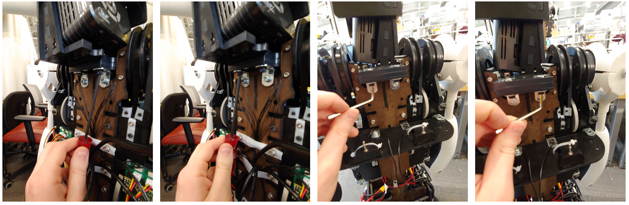
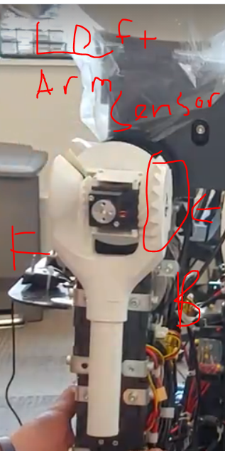
You will need to set the zero position for the two sensors in each arm. This is done in the calibration configuration where the joints should read zero.
The arm should be straight out and the abduction axis of the shoulder joint facing forward. The part of the shoulder 3d printed piece with the sensor should be closest to the back for the right arm while for the left arm should be calibrated with the sensor face closest to the front of the robot. The two images of the left and right arms almost in calibration (the abduction is not zeroed since it is not perpendicular to the module as with the left most animation image), that is, the proper alignment in one axis for each showing how the sensor should be parallel to different faces depending on while arm you are working with.
Below, the target calibration position:
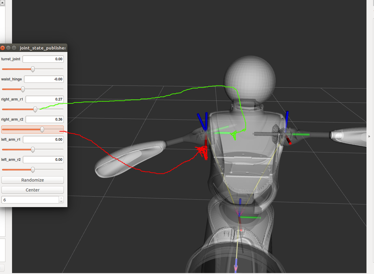
Right arm sensor alignment example:
Left arm sensor alignment example:
Flash the microcontroller for the arm you are calibrating with the code as instructed from quori_embedded; however, you will set the ARM_ZERO_POSITION variables in calibration.hpp to zero for the arm you are calibrating.
Next launch the controller file in quori_ros. You should now be able to view the sensor’s value by using rostopic echo to see the joint’s state. Use these value for their corresponding ARM_ZERO_POSITION variables. You can now flash the microcontroller with the update calibration. Verify the calibration was successful by reading the joint’s position in the zero configuration. The position should be reported as something close to zero.
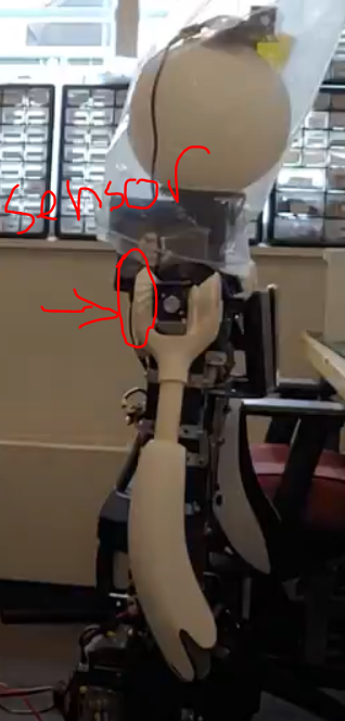
Waist
The waist has two sensors to calibrate. The raw value of each sensor is not displayed and so it is a bit more difficult to calibrate this. While there may be an easier option, here is one option for how to recalibrate the waist.
Each sensor for the waist is calibrated with the torso upright in its zero configuration.
The calibration value for the waist can be found by flashing the waist code from quori_embedded with the QUORI_CONFIG_ZERO_POSITION_WAIST values as 0.
You can then echo the joint’s state to get the proper calibration value for the waist.
For the QUORI_CONFIG_ZERO_POSITION_MOTOR, you will need to change the line with
states.measured[0] = -state->waist[0];//state->measured[0];
To
states.measured[0] = state->measured[0];
When you echo the joint’s position you will now be reading the motor position. Use this value for QUORI_CONFIG_ZERO_POSITION_MOTOR
Be sure to change the code back to its original state with
states.measured[0] = -state->waist[0];//state->measured[0];
Base
The base calibration does not require the microcontroller to be flashed. The calibration value is stored in src/quori_controller/config/calibration.yaml. To find the value to use for calibration set the value in the calibration file to 0. Then:
roslaunch quori_controller quori_control_holo.launchroslaunch quori_teleop quori_teleop.launch- Hold the left bumper LB and use the thumbsticks to rotate the top plate of the base into your desired zero heading. See teleop repo for more information on how to command the robot
rostopic echo /quori/base/pos_status- Use the value reported in the echo above as the new calibration value in the calibration file
Values
| LEFT ARM | RIGHT ARM | SPINE | |||||||
|---|---|---|---|---|---|---|---|---|---|
| Q# | QUORI_LEFT_ARM_ZERO_POSITION_X | QUORI_LEFT_ARM_ZERO_POSITION_Y | QUORI_RIGHT_ARM_ZERO_POSITION_X | QUORI_RIGHT_ARM_ZERO_POSITION_Y | QUORI_CONFIG_ZERO_POSITION_WAIST | QUORI_CONFIG_ZERO_POSITION_MOTOR | /opt/quori/quori_controller/config/calibration base_offset: | Head dx | Head dy |
| 1 | -1.8 | -2.0388 | 1.93 | -5.0388 | 0.18 | 0.9 | |||
| 2 | 0.9434 | 2.5247 | 0.5737 | -0.7704 | -2.007 | 1.6457 | 0.0944 | -2.5 | -1.65 |
| 3 | 2.9258 | 2.1684 | -1.1363 | -0.53 | -0.5515 | -0.8114 | 0.02606 | -2.65 | -1.75 |
| 4 | -1.6475 | 1.366 | 2.3041 | -2.2458 | 0.6527 | 0.1149 | 0.72 | -3 | -1.85 |
| 5 | 2.5998 | 2.7943 | -1.7496 | 0.6588 | -2.3031 | 0.6666 | 0.2982 | -2.5 | -1.7 |
| 6 | -1.8658 | -1.2782 | 2.6999 | -3.1018 | 1.4965 | 2.7852 | 0.583958 | -2.75 | -1.85 |
| 7 | -0.2711 | 0.4138 | -0.9802 | 2.12 | 1.7895 | -2.3996 | 0.201184 | -2.9 | -1.4 |
| 8 | -2.32 | -1.22 | 1.381 | -2.8062 | 2.328 | 0.9444 | 0.93102 | -3.2 | -1.9 |
| 9 | 1.582 | -0.0153 | -0.6412 | -1.0186 | 0.6627 | -1.3553 | 0.289568 | -2.7 | -1.8 |
| 10 | -2.7 | 1.273 | -2.4 | 0.016 | 0.405 | -0.7193 | 0.347 | -2.7 | -1.97 |
Microcode
-
Microcontroller for the arm, and waist modules: Teensy LC
-
Embedded Code for the arms and waist modules: https://github.com/Quori-Robot/quori_embedded
-
Microcontroller for the base: NUCLEO-F303K8 (remove and jumpers from the microcontroller before using)
-
Code for the base module: https://github.com/Quori-Robot/quori_embedded. For the NUCLEO microcontroller you may need to:
- Update your computer to have the latest driver https://os.mbed.com/platforms/ST-Nucleo-F303K8/
- Update the mbed to have the latest firmware update https://os.mbed.com/platforms/ST-Nucleo-F303K8/
Instructions for installing the software to the microcontrollers can be found on at the repository: https://github.com/Quori-Robot/quori_embedded
To replace a microcontroller you will need to make sure it has the necessary number of header pins solder on the board to plug into its receptacle. Use the broken or old microcontroller as an example.
Flashing Motor Drivers
There are four motor drivers that can be programmed. It is not recommended that you alter these. If you need to alter the program or recover the driver’s settings please use the following settings. Note that the Waist/Torso controller is the G2 version of the controller and needs the G2 Pololu program.
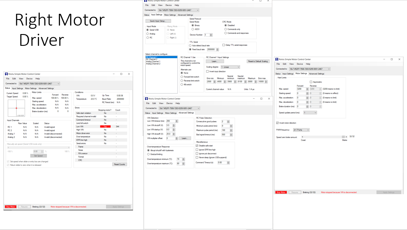
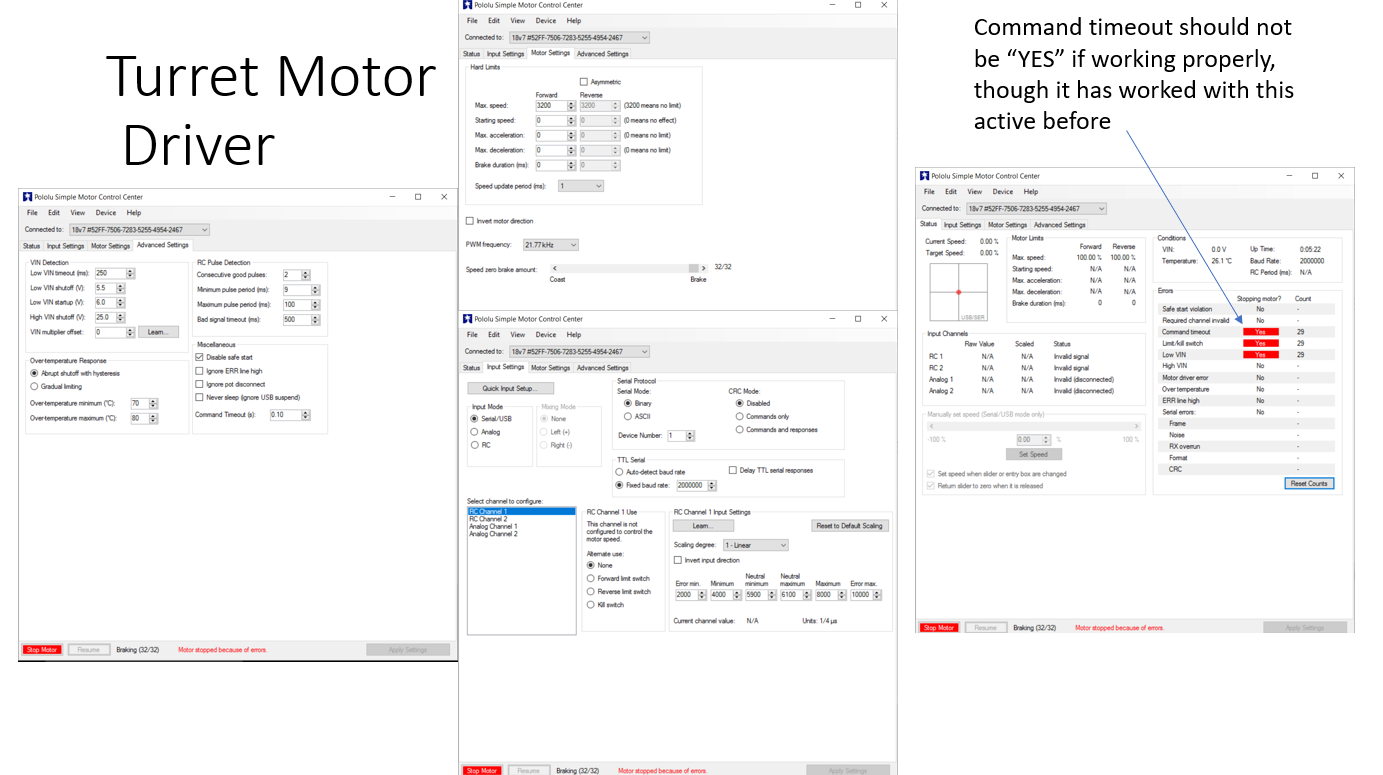
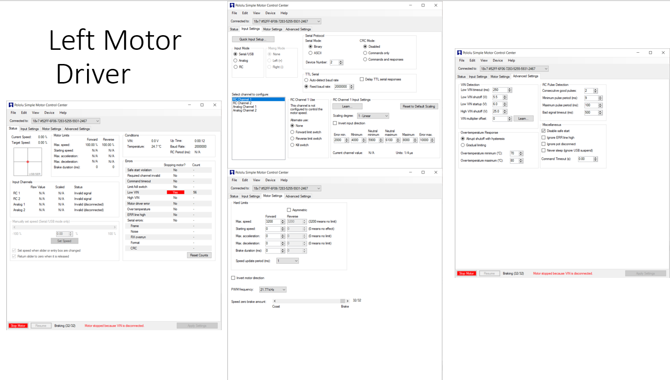
Base Motor Controller Settings
The three base motor controllers (Pololu Simple Motor Controller 18v7) are found soldered to a PCB on the base. Use a usb-mini cable to connect to the controller (You will probably need to partially disassemble to base to access all of the usb headers). The built in software is very convenient and easy to use. Most of the settings used on this project remain as the default. However, some settings were immediately changed. First, make sure that you go to advanced settings and make the Command Timeout (s), 0.1 second or 100 ms. Ideally the microcontroller sends a command to the motor drivers every millisecond, so this feature activates when the motor driver hasn't received a command in 100 cycles. This basically prevents the motors from moving when the arduino loses power or resets. Another setting that must be changed is the Device Number under input settings.This is the setting that determines which motor controller actually uses the serial packet sent out. In the current circuitry setup, assign 1 to the turret motor controller, 2 to the left motor controller, and 3 to the right motor controller. Also make sure that
- disable safe start selected
- set the device number right(3) left(2) turret(1)
- change baud rate to 2000000
- check which motors need to be inverted
- You may have to test this.
- set motor command timeout to 0.1
The images below are for reference. Read the instructions first as some values may need to be changed such as the “motor direction inverted” parameter
Waist/Torso Motor Controller Settings
You should make sure the controller is programmed first. https://www.pololu.com/docs/0J77/3.1 The waist is the G2 motor controller.
Use the following settings:
-
Input Settings
- Baud rate: Automatic detect
- Motor ID:
1
-
Motor Settings
- Current limit
- Measure the current calibration
- The easiest way to set the “Current offset calibration” setting is to connect power to VIN, make sure the motor is stopped, and then click the “Measure” button to measure the offset and automatically change the setting.
- Set the current limit to 4A
- Measure the current calibration
- Invert Motor Direction
- Use the motor controller software to command a positive speed. If the motor rotates CCW (axis pointing into the robot from the motor shaft) and thus the Torso CW( a forward bow towards 30 degree limit) then the direction is correctly set. Otherwise, toggle the “Invert motor direction” box.
- You may need change the command timeout to
0.0temporarily to do this.
- You may need change the command timeout to
- Use the motor controller software to command a positive speed. If the motor rotates CCW (axis pointing into the robot from the motor shaft) and thus the Torso CW( a forward bow towards 30 degree limit) then the direction is correctly set. Otherwise, toggle the “Invert motor direction” box.
- Advanced Settings
- VIN low shutoff: 3.0V
- disable safe start selected
- Command Timeout: 0.1
- Current limit
Hardware
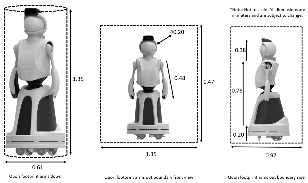
Quori is 1.35m tall, consisting of an expressive upper body attached to a omnidirectional mobile base.
Key Features
Key Dimensions
The four hardware modules – head, arms, torso, and base – are described in the following sections, along with their power and sensor systems:
Head
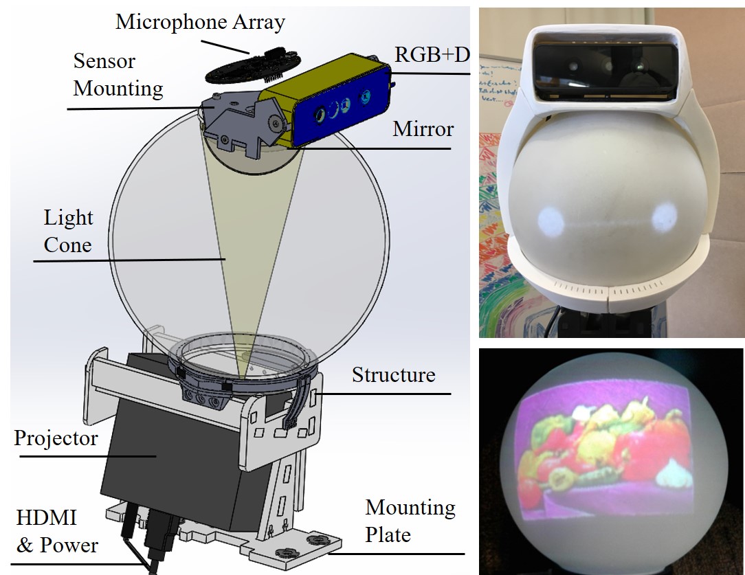
Quori's head module uses a retro-projected animated face (RAF) system. It consists of a small projector (115mm x 46mm x 105mm) and a domed mirror to map a projected image onto the inside of specially-coated thin sphere.
These components fit within a compact space approximately the size of an adult human head (200mm diameter) and weigh about 975 grams (excluding the RGB+D camera and microphone array). Software for using the head is provided and can be found in the Software section.
The projector is an AXAA P5 (US $290) with key properties: it is rated to provide 300 lumens, last 20,000 hours, and have native 1280x720 HD resolution; however, only $\sim$132 lumens are available to the spherical surface since the image reflected on the spherical head is a circle inscribed inside the projection rectangle. The projector is affordable (at US$290), has intermediate brightness, and short throw (20cm creates a focused 7.5cm x 12.7cm image). It creates a color image that is visible in most illuminated indoor environments where there is no sunlight saturation (Fig.~\ref{fig:headcad}, top). %
The mapping of projected images onto the sphere's surface is not uniform---the resolution is dense near the top of the head and sparse near the neck. The least dense equatorial line is approximately 200 pixels, compared to the highest ring, which has over 2,000 pixels; thus, creating expressive faces to be displayed on the spherical surface via a projected image is not trivial. Our mapping algorithm transforms pixels on the sphere to pixels in a 2D image to be sent to the projector. Details of the design and mapping used to project images to Quori's head can be found in our previous work \cite{weng2018low}.
The illusion of motion (e.g., head shaking, nodding, and gaze directing) can be produced through projection. Since the robot's head is a rotationally symmetric sphere with no protruding features (e.g., no nose or ears), head rotation can be simulated by projecting the image of a face rotating on the sphere without requiring additional motors or neck DoFs. Gaze direction can be simulated by coupling animation of the eyes with horizontal rotation of the whole upper torso ($M_T$ in Fig.\ref{fig:basecad}). The waist joint (Fig.\ref{fig:torsocad}) may also be useful in supplementing gaze, especially for interactions below or above the neutral gaze of the robot (e.g., for users who are shorter or taller than the robot) or for objects very near or far away. Sensors in the head can be replaced via fasteners on the sensor mounting plate. The camera field of view is discussed in Section~\ref{subsec:PowSysDesign} and shown in Fig.~\ref{fig:camerafov}.%
Sensors for Interaction
Stereo speakers mount to a shelf on the upper torso behind the chest panel allowing for ample volume (60 dB SPL at 3 meters). Slots in the helmet provide the illusion of sound being produced in the head.%,
A ReSpeaker 2.0 four-microphone array mounts to the top panel of the helmet for sound localization and speech recognition (Fig.~\ref{fig:headcad}). To test the sensor placement effectiveness for speech recognition, we performed a word error rate (WER) experiment using ten prerecorded English phrases produced from a hardware speaker at three distances (0.1m, 0.5m, and 1.0m), yielding an average WER below 13%. Additional or replacement microphones can be mounted inside the helmet.
An RGB+D camera mounts atop the robot's head to the sensor plate and fits inside the helmet (Fig.~\ref{fig:headcad}). The position of the camera gives the robot a $60^{\circ}$ H x $49.5^{\circ}$V FoV that follows the robot's gaze direction.
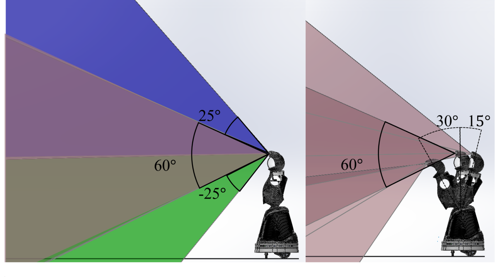
The camera is also plainly visible, which helps to set reasonable social expectations for what is in its FoV (Fig.~\ref{fig:camerafov}); this FoV can be manually adjusted to $\pm 25^{\circ}$. The current camera is an Orbbec Astra Mini\footnote{\url{http://shop.orbbec3d.com/Astra-Mini_p_40.html}} in a DuriPOD Case\footnote{\url{http://shop.orbbec3d.com/DuriPOD_p_47.html}}, which is 120mm x 37.5mm x 32.5mm, but can be easily replaced.
Quori's RGB+D FoV can be positioned by two means, manually and by rotation of the torso while the robot is moving. Left: FoV of the camera when positioned manually to neutral(red), $25^{\circ}$ maximum angle up (blue) and down (green). Right: Discrete sweep of the camera FoV at neutral position for three torso positions, $30^{\circ}$ forward, neutral, and $15^{\circ}$ backward.
Joints
The following section will provide a high level overview of the joints of the robot and its kinematics. More detailed information can be found at the quori_description repository.
Joint Limits
- The base joints are all continuous revolute joints.
- The waist joint is revolute and has a range of
[-0.47,0.22], and is limited in both the low-level microcontroller and the quori_ros via the urdf. Mechanical stops exist to prevent the waist from going past these values. - Each arm has two degrees of freedom. The pitch and roll for each arm is limited by the urdf. The roll is further limited in the low-level microcontroller code. The pitch degree of freedom can theoretically be used continuously if the mid-level software is updated.
Joint orientation Information
Arms
Gestures are a key part of natural communication in social interaction. Quori's arm design is affordable, modular, safe, and expandable. The shoulder module (see illustration below) has two DoFs based on a design by Whitney (2014). However, our design differs in the use of 3D-printed bevel gears instead of a capstan cable drive. In addition, to save costs and complexity, we chose to not gravity-compensate the arm, thus, enabling the elbow and arm modules to be changed. The arm is driven by brushless DC motors through a transmission consisting of a friction wheel pair and a timing belt speed reduction (see illustration below, left). The entire arm module mounts to the spine with fasteners.
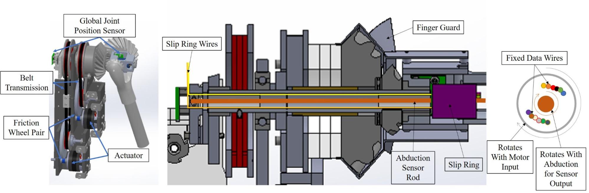
Left: CAD model of the arm module. Center: A sectional view of the compact differential transmission. Right: Section view of the arm differential highlighting how the torque is transferred while allowing 12 wires to be available to the arm with continual shoulder rotation.
Notable features of the arm design include resolution of the joint positions, drive motor abilities, and general safety considerations. The approximate resolutions of the joint position sensors are 0.022$^{\circ}$ and 0.075$^{\circ}$ for the shoulder joint (through the use of magnetic encoders on the output shafts, Fig.~\ref{fig:armcad}) and the drive motors, respectively. Access to both motor and shoulder positions allows the system to check for slippage between the friction wheel pair or timing belt stages, as well as perform automatic calibration upon boot-up of the system.
The arm motors can produce approximately 0.15Nm and are able to rotate at approximately 16 revolutions per second, resulting in shoulder joint speeds up to $\sim$1.2 radians per second\footnote{This is based on the motor properties at 12 Volts operation.}.
The abduction/adduction DoF has a range of $\pm70^{\circ}$, and the circumduction DoF is continuous. The arm design is expandable; we designed access for power and/or communication for further joints in the arms (e.g., an elbow), while allowing the arm to rotate continuously. We achieved this via a shoulder joint slip ring with six available wires (rated to 2 A) (Fig.~\ref{fig:armcad}, right). As an example, two servo motors can be added as they only use three wires each. More DoF may be added through multiplexing. %
We used the following operational safety measures: a torque limit on the drive motors; a low-mass, low-inertia arm mechanism and structure that is safe according to the Head Injury Criterion \cite{zinn2004playing}; and a friction wheel designed to slip in case the motor generates too much torque or the arm is back-driven. %
Our primary goals in arm design were to ensure safe and precise yet fluid motion for expressivity, while maintaining affordability. Manipulation (i.e., carrying some payload or applying forces to the environment) was explicitly \textit{not} the goal of our design; thus, we used light-weight limbs and IQ Control's position controlled, direct drive, and brushless servo motors\footnote{http://iq-control.com}. Arms that would be expected to lift, push, or pull would need structural stability that typically leads to heavier and more expensive designs. Furthermore, heavier arms require larger and thus more expensive motors to move. Lower-cost motors or servos could be used at the expense of precision for the case of brushless DC motors \cite{piccoli2016anticogging}.
Torso and Waist
Quori's torso module not only supports the arms and head, but also has one DoF to lean forward and backward. Here is the torso and waist hardware overview on the left, and the extreme positions the robot achieves on the right:
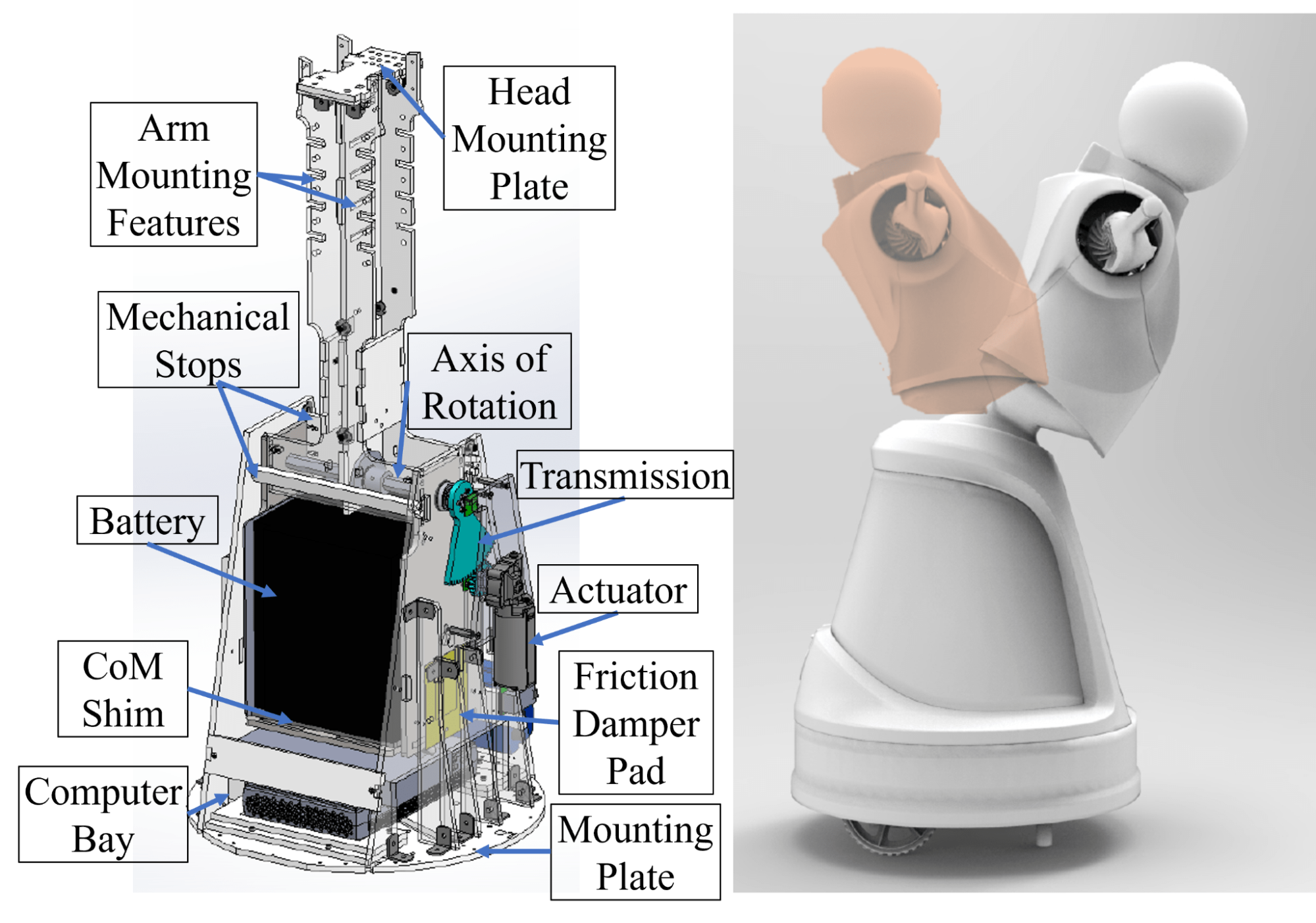
The robot can bow forward 30 degrees or lean back 15 degrees. Mechanical limitations on the positions prevent self-collision.
This design also minimizes acceleration-induced swaying generated during the motion of the mobile base, leading to fluid, natural, and appealing tunable motion.
The batteries and onboard computer are stored in the torso.
The spine allows for easy attachment of additional custom hardware, such as arms or a head. A new head module can be attached to the spine using the provided mounting holes. The arms have similar mounting possibilities---shelves/ledges can be added to the spine for additional accessories, such as sensors, tablets, trays, container mountings, etc.
Considerable space is allotted for batteries and a computer\footnote{Quori currently ships with a nuc8i7hvk: Intel$^\copyright$ Core$^{\text{TM}}$ i7-8809G Processor with Radeon$^{\text{TM}}$ RX Vega M GH graphics (8M Cache, up to 4.20 GHz)}: 17cm x 15cm x 21cm and 20cm x 20cm x 7cm, respectively. Currently, the battery bay space fits a 40-ampere-hour sealed lead acid battery that powers the whole robot. While many options exist for small form factor computers, we have ensured sufficient space for a computer with computational resources suitable for real-world use, such as a NUC\footnote{\url{https://ark.intel.com/content/www/us/en/ark/products/126143/intel-nuc-kit-nuc8i7hvk.html}} or NVIDIA Jetson TX1\footnote{\url{https://developer.nvidia.com/embedded/jetson-tx1-developer-kit}}.
Next, we present our approach to designing the single DoF waist which involves gravity compensation. The transmission design is also discussed.
Gravity Compensation Design and Tuning of Waist Joint
Robot motion is often caricatured as jerky with overshoot; for example, a person pretending to be a robot might exaggerate leaning backwards as they start to walk forward, then sway forward and back just as they stop walking, as a cantilevered stick might do as a damped oscillator. Avoiding these types of motions typically requires expensive, strong motors and precise feedback.
Alternatively, adding mass to shift the center of mass (CoM) can change this behavior. A CoM below the axis of rotation causes the torso to lean forward during acceleration (opposite to the prototypical robot caricature motion), while a CoM at the axis of rotation reduces the motion. %
Affordable actuation of the waist can be achieved with a counterbalance metronome design. This design leverages the mass of the robot's battery to offset the moment of the upper body of the torso, head, sensors, and arms. The moment that needs to be balanced changes, as the balance depends on the position of the arms $\phi_a$ which may be moving. This model is used for tuning the CoM of the torso and waist actuator torque is shown below:
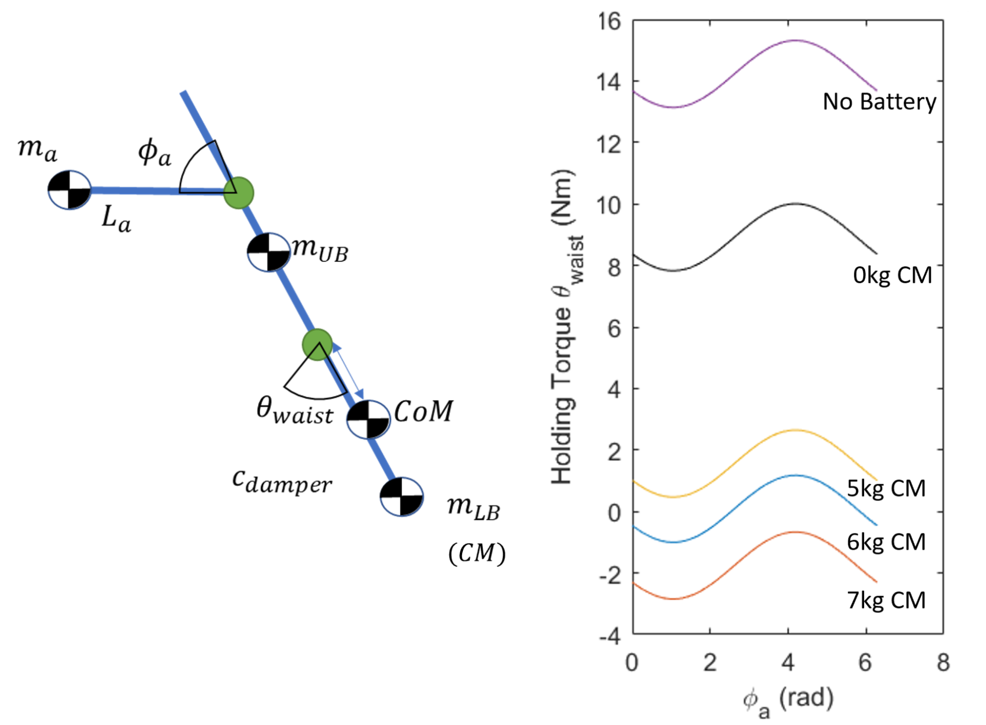
The masses are separated into the upper body mass $m_{UB}$ (head and arm transmission), the arm link mass $m_a$, and the lower body mass $m_{LB}$ (battery and counter masses). Right: Maximum waist holding torque curves used to select a starting counter mass (CM) configuration for the torso. The lines are produced by simulating the arms flexion, $\phi_a$, in order to produce the maximum waist torque, $\Ddot{\theta}_{waist}$, to hold the most difficult position of bowing forward.
The model abouve shows the torque required to hold the torso at its max bow position as the arms rotate in the plane. The effect of the extra counter-mass, the battery, and an ideal tuned counterbalance design is shown too. In its most difficult bowing position, the waist experiences a 16-Nm moment without counterbalancing (purple line). It is very challenging to find a motor with this capability, that is also small enough to fit in the required space and is affordable. Instead, with proper counterbalancing, the battery and an extra 6 kg (blue line), the peak torque requires less than 2-Nm.
The major drawback to this counterbalance design is the increased inertia of the torso. The waist does not need to move very fast---less than 1$\frac{rad}{s}$---nor accelerate faster than 1$\frac{rad}{s^2}$, which leads to a max accelerating torque of about 2.5 Nm; for reference, the max required static holding torque of the final design is approximately 2.5-Nm.%
To realize the counterbalance design, we used the model as a starting point (blue line), and manually tuned the final counterbalance configuration during construction. The battery bay structure (made from steel) provides both a stiff structure to support the battery and contributes about half of the needed 6 kg counter-mass. Steel plates and bars underneath the battery allow for high-resolution calibration of the counter mass. Proper calibration shows gauge values below 3.0 Nm, a torque achievable by our lower-cost (i.e., less than US $100), low-profile actuator. This actuator---a window motor---is also quiet, especially when compared to small but high speed motors with larger gearing.
Waist Transmission Design
A non-backdrivable transmission was chosen to minimize the energy required to bow so holding positions requires zero energy.
An optional locking pin feature allows for the torso motion to be locked for shipping or if waist actuation is not desired.
Friction damper pads on each side of the battery bay add dampening to the waist motion. The pads consist of soft foam and a PTFE sheet fastened to the battery bay, which push against an ABS plastic sheet. This design compensates for gear backlash and compliance in the structure and actuator and greatly simplifies smooth control. The damper increases the torque required to rotate the torso, but this effect was measured empirically to bring the waist motor torque to no more than 3.0 Nm, which met our goal.
Mobile Base
Power
Power System
Quori's power system was designed to operate untethered with the use of a 12V 40AH battery, which is also used as a counter balance. The battery is a Sealed Lead Acid (SLA) Absorbent Glass Mat (AGM) chemistry battery that is affordable (compared to lithium-based batteries) and stable without losing charge over long periods and has minimal risk of fires or acid spill. %
Shipping is also simplified as the battery only requires the use of a sticker stating ``non-spillable battery'' instead of additional regulations or costs. A potential downside of SLA batteries is the low energy density and high mass; however, we take advantage of this as a counterbalance, as discussed in Section~\ref{subsubsec:TorsoDesign}.
Most of the robot's subsystems are 12V-based; the only significant voltage switching occurs in a DC-to-AC power inverter, which allows for a main computer (e.g., a laptop) to be used on Quori without requiring the selection or design of an additional DC-to-DC voltage regulator. A simplified diagram of components is presented in Fig.~\ref{fig:powerOver}.
The robot can also run in a tethered mode when not mobile.
See Recharging for more information on how to charge the robot.
Power Configurations
You can power your Quori with the battery or use an external power source. Here are a few suggestions. Make sure your robot is off (the main breaker) before modifying any power configuration.
Battery Only
This is the default configuration for Quori. Make sure the following is correct.
- The battery is plugged into the robot’s main breaker
- The PC and Projector AC plugs are plugged into the inverter
PC and Projector External
Here the PC and projector plug into an extension chord into 120 AC Voltage
-
Turn off the inverter power switch
-
Unplug the PC and projector power cables.
-
Plug the PC and projector cables into a properly rated power cable. Be mindful of this cable if the robot is connected to the base.
All External Power
You will need a DC power supply rated for 12 Volts at least 30 Amps to power the actuators. The power supply will need a Female XT-60 connector and will plug into the power in cable.
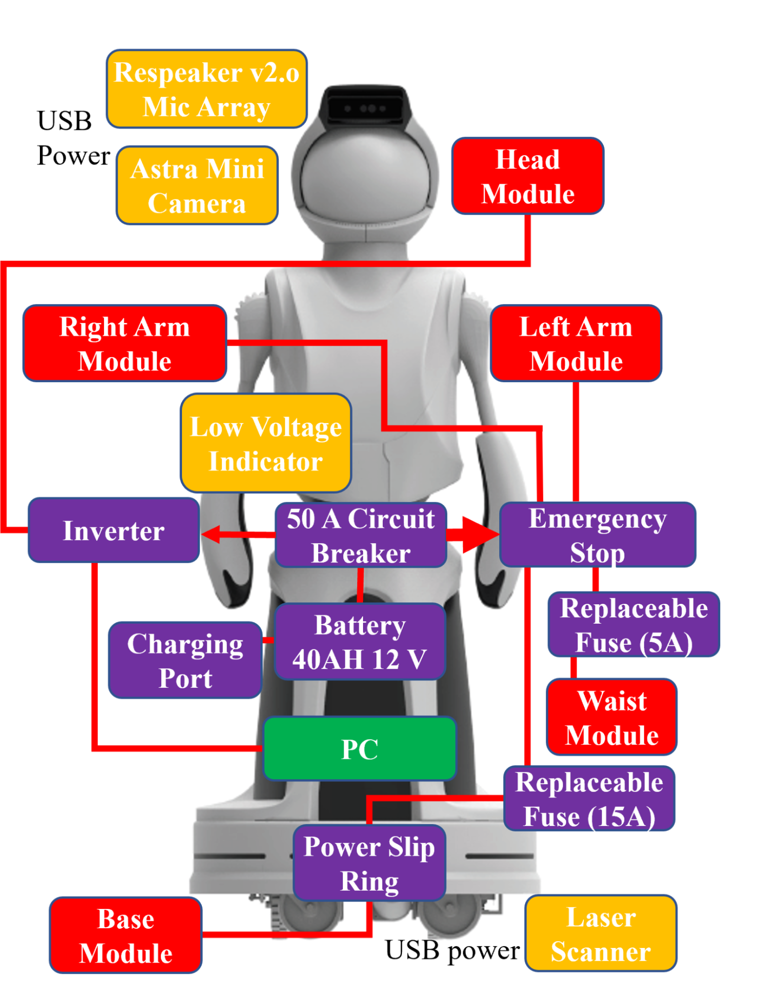
Above, the 12V DC circuit for Quori. Motor controllers receive power directly from the battery, while sensors receive power from the computer. The emergency stop controls power to the motors, but allows the computer and projector to remain on. The power charging port is within the battery bay.
- Unplug the batter cable from the robot cable and cover the batter plug with a cover
- Plug your DC power supply into the now open male XT60 connector on the robot
- Note: A variation of this configurations uses both a DC power supply and AC external power. You can use a smaller DC power supply and implement the steps from “PC and Projector External”.
Electronics
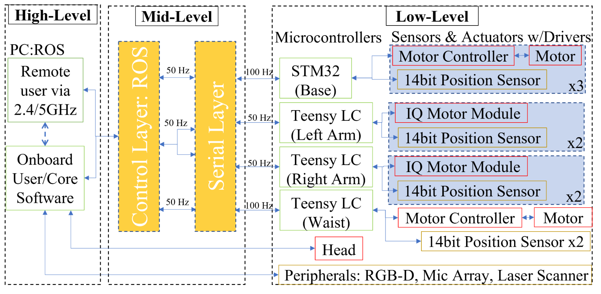
Each of the sensors and main components connect via standard connectors and communication interfaces for simplicity, modularity, and potential future reconfiguration.
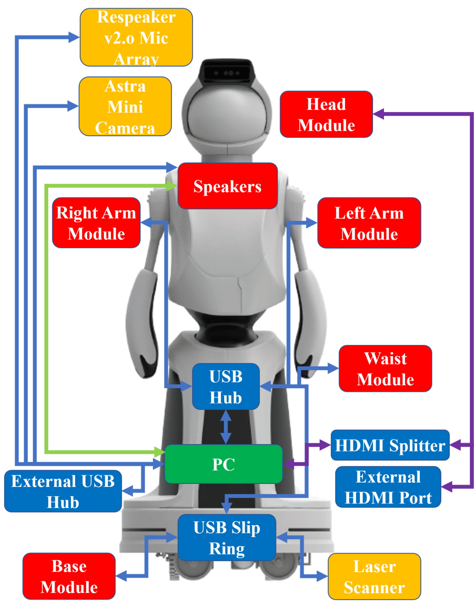
The figure above shows the components and connection types. Data are transferred via standard methods of USB 2.0 and 3.0 (blue lines), audio jack (green lines) and HDMI (purple lines). Module and sensors are readily modified or replaced with other devices that communicate over USB. A four-port USB hub and a one-port HDMI port are accessible from the back of the robot without removing any components.
The main connection type is USB with all connections using USB 2.0, except for the USB 3.0 RGB+D camera (Quori's default PC has multiple USB 3.0 ports for future upgrades). HDMI transmits the head image data, allowing for future modifications. A stereo audio cable from the PC 3.5-mm audio port transmits audio to the chest speakers. A USB and HDMI port are accessible from the back panel of the robot for programming and debugging.
Computer
Quori currently ships with a nuc8i7hvk: Intel© CoreTM i7-8809G Processor with RadeonTM RX Vega M GH graphics (8M Cache, up to 4.20 GHz). It has a 500 GB SSD and 16 GB of RAM
See System for more how to configure the PC.
Microcontrollers
Quori has 4 microcontrollers that can be programmed. This is not recommended as the embedded software is designed to handle low level motor control such that the user does not need to think about the code and thus the user only needs to program on the computer to interface with the actuators over serial. That being said, in the case a microcontroller breaks you may need to reload the embedded software to your robot. Here is the information you may need.
Modular Configurations
You can reconfigure Quori with new modules or use some of its module’s independently. See the Receiving and Shipping Section for instructions on how to attach and remove modules. If you do not use Quori in its default configuration you may need to modify the quori_controller configuration. Here are a few examples to consider:
Locking the Waist
An optional locking pin feature allows for the torso motion to be locked for shipping or if waist actuation is not desired. You can do this with two torso locking M3 bolts that are 60 mm long. The battery will not fit if these are screwed in too far so you must be careful when inserting these. If you do not use the waist motor remove the 5 Amp fuse near the motor line. See this video for reference. Note that there are four options for these locking positions.
Using the Base Module Independently
You may want to mount your own robot the the base module. The base module has 14 M3 inserts in its mounting plate. See FILE for mounting plate dimensions. To control the base with your own robot you will need to give the base power and ROS to send commands.
For power you will need 12V at atleast 6 Amps to plug into the base’s XT60 cable. For data, you will need to plug the base’s USB cable into a computer running ROS. ROS topics for the base can be found on the github repository.
Using the Head Module Independently
The head module can be detached from the torso by the four mounting M5 fasteners and the power and HDMI cables. The projector will turn ON if it sees power from its AC power adapter. You can detach the power adapter from the Quori if needed. The projector will automatically select the HDMI input once the projector is connected to a source over HDMI.
Using the Upper Body Module Independently
The default quori_ros software currently does not support control of the torso without the base module being attached. If you use the Torso without the base be sure to cover the base XT60 connector with a cap or electrical tape to prevent risk of electrical shock and that port shorting. You can modify the quori_controller configuration to not register the base. You will need to remove the base_controller from quori_control_holo.yaml and the base device from the params.yaml.
Swapping out Modules
You may want to use your module on Quori. Please note that any hardware modification will most likely require updating the core ROS software which loads the model of the robot and allows for joint control and feedback.
Troubleshooting
Computer
The PC will not turn on
-
If you are running the PC from the inverter on the robot (for battery power or external AC2DC) Check that the power switch on the inverter is set the the "ON" position.
-
Try holding the PC power button down for a 2-5 seconds
-
Try testing the PC connected to AC power instead of the inverter
-
Try running the PC from an external power source. If this does not work check for unseated power cables
-
Check the power cable has not become unseated at the DC end which plugs into the computer (see blue circle)
-
-
Check the AC power cable plugging into the power brick. You can access this from the back-right of the robot. The power brick is between the computer top and the battery bay bottom
-
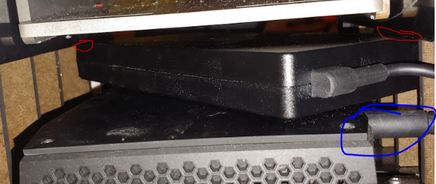
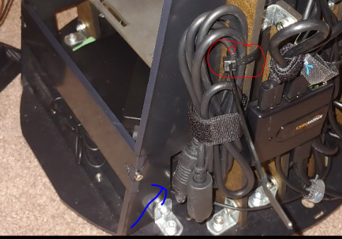
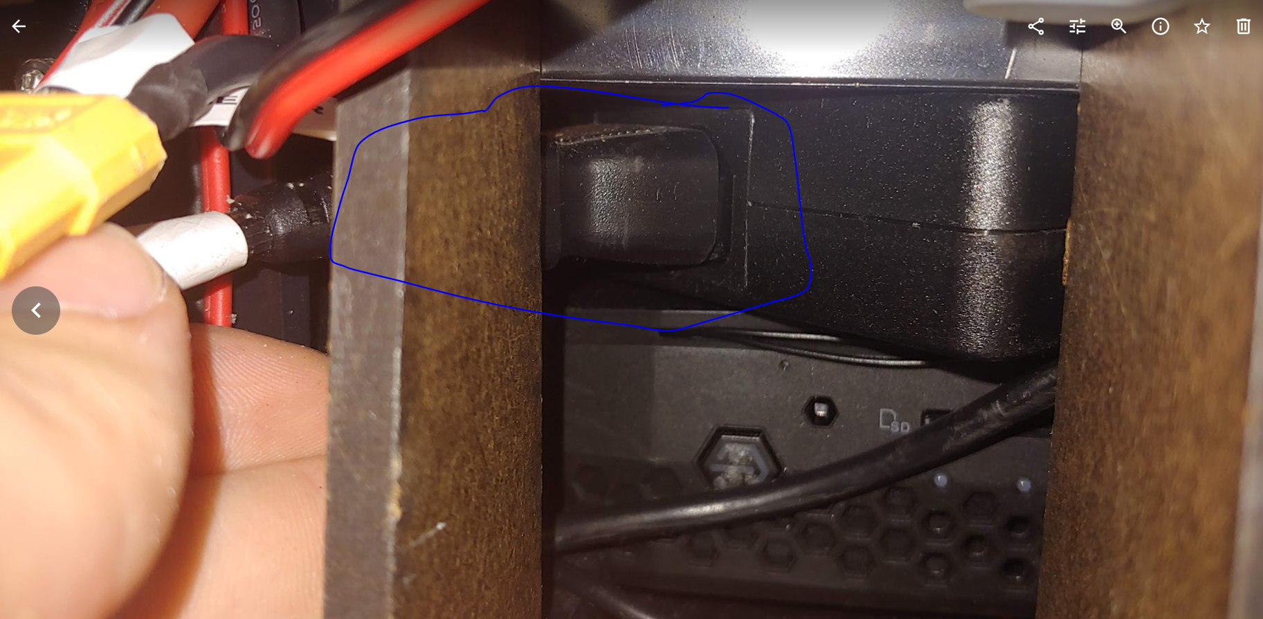
Communication/Control General
Module will not connect to software control
- Check the micro usb cable is plugged into the microcontroller. If not you might get a joint state failure message. Check at the USB A and micro usb ends of the connection
Joystick Node Control Not working
- The "Mode" button LED should not be on. Press the "Mode" button to turn the LED off. If the LED is on the buttons and axis may not work properly
Laser scanner:
-
Operation Time Out things to try:
-
Unplug and replug the white 5 wire cable that connects the laser scanner to the usb cable.
-
Unplug and replug the microUSB cable side
-
Unplug and replug the USB A side into the hub
-
USB port binding error
-
Unplug and replug the white 5 wire cable that connects the laser scanner to the usb cable.
-
Unplug and replug the microUSB cable side
-
Unplug and replug the USB A side into the hub
Head
The head is not displaying
-
Is the projector on?
- If the projector has power a blue screen should show in the head and the LEDs on the projector case should be blue.
-
Is the HDMI cable plugged in and working properly?
- Make sure the cables are connected properly
- Try to plug a different cable into the projector to test if the cable or the HDMI switch is working.
-
The HDMI splitter might not be functioning properly. Sometimes unplugging the usb power to the splitter can solve the issue. Alternatively, plugging the usb power in might also help. Do this when the robot is shut off, that is do not do this while the robot is powered on.
-
If the screen is only displaying one shade of colors, you might also try unplugging the projector cable at the projector (the barrel jack) and inspecting for any debris and plugging it back in.
Arms
The arms are not moving
-
Check that the arms are not past the safe position. There is a limit in the microcontroller for the abduction/adduction DOF that when it passes it the arms are not allowed to move. You can carefully lift or lower the arm to the neutral and try again. Be sure to shutdown the motor power before backdriving the robot
-
A possible USB problem
- Check that the two microcontrollers have their orange light lit.
-
A possible power problem
- Did the motors make a boot up noise when power was added? They should.
- Are all of the power cables going into the arm plugged in securely? If they fall out you can add a zip tie to hold them in place.
The arms are not moving smoothly or are stuck
-
Check for debris in the transmission using a flash light.
-
Check that the friction roller (blue rubber on the motor shaft) is not loose and spinning freely wrt the shaft
-
Try replacing the friction roller. You may have a roller that has hardened over time or a flat spot in the rubber or a defect that is leading to binding.
-
Replacing friction roller in arm
Base
No data connection
- Check that all the usb plugs are plugged in. When the robot is connected correctly to a computer the microcontroller will have a light on and so will the position sensors and the USB hub. The laser scanner will also spin.
The Base is not moving
- Check if the fuse is blown. If it is blown you will need to replace the fuse before the module can operate. Be sure to identify the source of the fuse blowing before replacing the fuse as it would be best to fix any issue first.
Torso:
The Torso is not moving
- Check if the fuse is blown. If it is blown you will need to replace the fuse before the module can operate. Be sure to identify the source of the fuse blowing before replacing the fuse as it would be best to fix any issue first.
The Torso motion is jerky.
-
The counter mass may not be correct. Check the default configuration for the counter mass. There should be two steel plates at underneath the SLA battery. The battery MUST be centered in the battery bay.
- Depending on the configuration of the robot the counter mass may need to be reconfigured. The nominal balancing is achieved with two plates under the battery. The process can be found* here* to verify this or to counter balance the system under another configuration.
-
Check that the motor gear is not slipping
-
Check that the torso hub (large metal flanged hub at the center of the robot) connection to the hex shaft is secure.
-
Check that the wedge gear connection to the hex shaft is secure.
-
Check that the data and power wires the route up the torso frame and into the upper torso that is rotating do not get caught as the robot rotates.
-
Check that the battery is secured well by the two velcro strap. The battery may shift if it is loose which will cause the motor to struggle to move the torso smoothly.
-
Make sure the power brick for the PC is securely under the computer bay ledge. If it is not the the power brick might not be level and may go above this height. If the brick is above the computer bay ledge it can collide with the torso causing the torso to stop or the power to turn off. There should be 19mm of clearance between the computer's power brick and the steel bottom plate of the battery bay. If there is less than this (especially less than 14 mm) you should check that the PC is seated well in its bay and there is no debris caught under it.
Battery Installation
Difficulty installing the battery
-
Make sure the cable is not getting caught when you install the battery
-
The battery fits snuggly into the steel bay. The battery should fit well if you insert the battery such that it is aligned with the compartment. Inserting the battery at an angle could lead to it getting stuck.